Make a Contact Microphone and Preamp
developed in Aug 2020 in parallel to the DIY Soundscape Box workshop series
Acknowledgement
We acknowledge Aboriginal and Torres Strait Islander peoples and their continuing connection to land and as custodians of stories for millennia. We respectfully acknowledge the land on which we all meet today, and pay our respects to elders past, present and emerging.
SUMMARY
The Following describes a engaging and practical 2 hour workshop pitched to introduce the basics of :
- Soldering
- Electronics (an amplifying circuit is a component in many if not most of the devices around us in the modern world)
- Reading and interpreting a circuit diagram
- Laying out a basic circuit for testing on a breadboard and a protoboard.
This intro to electronics is also paired with the engaging and addictive takeaway. Discovering the hidden (ignored) sonic world around us by playing with a contact microphone can be a gateway drug to audio electronics and can change the way you think about the sounds around you.
Some people will also come for the basic electronics and discover sound and vice versa)
Background
In Aug 2020 during the COVID 19 Pandemic, Applied Creativity developed and delivered a trial of a series of 2x 2 hr Soundscape Box workshops over Zoom. You can see the documentation of these workshops here Developing the DIY Soundscape Box Try It. These soundscape workshops were mainly concerned with the making, customising and sonic experimentation with the Soundscape box (a small modular cardboard resonator box in a kit with a small selection of hardware and craft items) over Zoom.
Making a contact microphone was a relatively “simple” component that we have made with participants in about 15 min in the past. Normally we would include this as a 3rd face-to-face workshop in the space with the Soundscape workshops. Its an engaging and accessble activity to introduce participants to some really basic electronics. However, Health and Safety concerns (inexperienced, unsupervised participants using hazardous tools and material in their own homes) and the fact that participants may not have the required tools, meant that this component was left out of the series. We instead planned for these to be fabricated, tested and included in the kits. However in early testing of the workshop activity on contemporary consumer electronics (PC Laptops and Mac, and smartphone we identified 2 significant complications.
Complication One - TRRS
Where it had been easy to plug a homemade Contact microphone, with a mono plug [2 pole / TS (Tip Sleave)] or a stereo balanced plug [3 pole TRS (Tip Ring Sleeve)] on the end, into the the mic socket on a PC and make a recording without much fuss, over the last 4 or 5 years the TRRS (Tip Ring Ring Sleeve) or 4 pole 3.5mm plug / socket has become the standard way of providing audio input/output to headphone/mic combo headsets on smart phones and laptop computers. Only computers with a dedicated sound card (or pretending to be fancy) have a dedicate Mic in socket. If you want to plug in a stand alone Microphone you need to use an audio interface (usually connected via usb) or purchase a converter ( the cheap ones rarely are cross platform). To confuse this further different manufacturers use a different wiring TRRS standards. There are many convenient posts online that will lie to you about that these standard are 
Initially after identifying this issue we planned to make a converter to allow our contact microphone to the range of devices that participants would be using in the workshop.
We also eventually identified that it was not a different standard being used by osx and windows/android devices but the lack of a sufficient load in the microphone that was stopping the different devices from recognising our contact. Most of the devices we tested Macbook, PC laptop and android phones began to more readily recognise the plug as something with the addition of a 1.5 Kohm resistor across the source.
Complication Two - Active Noise Filtering
The simple form of the homemade contact microphone I have made with participants in the past did not have a preamp (it was just a piezo soldered to hacked headphone cable and dipped in plastidip to make a hydrophone) and only produced a weak signal… But that was ok because we cranked up the gain and amplified/ tidied it up in post.
Contemporary consumer electronics like laptops and smart phones, and applications like Zoom now have built-in Noise canceling filters to make ensure that audio generally plug & play. Actually wanting to capture weak, noisy signals is a 1 in a million use case - its only weird artists and mad scientists that would be interested in this.
In most cases a weak or noisey signal gets filtered out as a fault in modern devices and so it has become almost impossible to get contemporary consumer electronics to consistently recognise a simple contact microphone so we can make a recording. Its possible apart from the plug & play cause, weak signals also get filtered out as a security measure - to guard against weird signals like what we get out of a contact aren't someone trying to hack into our smart phone.
After some frustrating dead-ends and setbacks it became clear that making a Contact Mic with a preamp was the only way to consistently could get around these complications.
How hard could it be? 
Contact mic WITH Preamp as the solution to these issues
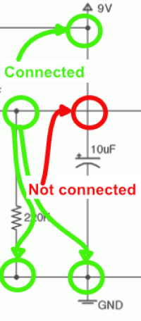
So the solution to these issues seemed to be building a Contact Mic with a preamp and Collins Lab: DIY Contact Mic seemed be be a straight forward circuit to build. After correcting a small misinterpretation of the circuit diagram (connecting things that should not be connected - see the image below)
we had a small success.
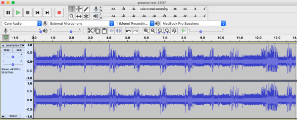
With this Collins lab circuit plus a 1.5Kohm resistor added over the output identified as R5 on the circuit diagram below ( to serve as a load to be recognised as a microphone by the device) we were able to produce a signal on PC laptop, macbook, iphone and an android phone. This signal was however very weak and included alot of noise. This result was encouraging as a proof of concept but would not be suitable for the workshop.
Collins Lab actually referenced James T Dawes webpost on Preamps who gives a great description of how Transistor Preamps work and how the circuit can be optimised to be compatible with different use cases and the type of JFET you are using.
Increasing Gain and Reducing Noise Floor
James T Dawes suggested adding a capacitor across the source pin of the transistor and ground (C1 we tried a 4.7uF ). This Cap is there to reduce the noise floor on the source.

The next day we replaced this with a smaller value capacitor (1uF) which also increased the gain. In a final prototype C1 was again replaced with a smaller 0.1uF capacitor that seemed to deliver the right level of gain balanced with a lower noise floor.
 that was fabricated on Protoboard and mailed out to participants.
Workshop Plan
Preparation
Step Zero
Step One
Introduction
Today we'll be making a ….
Whats a contact Mic?
How Do people use Contact Microphone
===How do they work
The Colins Lab Homebrew Piezos video on YouTube provides a great description of how Piezo's work and how you can make your own.
How Does the preamp Circuit work?
Testing the Circuit on a Breadboard
Step 1
Work out where ground, power and signals are coming in and out Whats the heart of your circuit Try it out on paper Use jumper wires if you need to extend
Assembling the Circuit on Protoboard
Soldering Tips
Prototyping Tips
Take what you learnt on the breadboard and apply this when you workout your protoboard layout on paper Spread out consider mechanical strain
Step 1
- Cut Protoboard and cut cables to length
- cut and prep heat shrink - make sure heat shrink and socket covers are on your cable before you start soldering
- Place and solder components
- Check for dodge solder joints and shorts as you go
- Again consider leaving sensitive components till last


