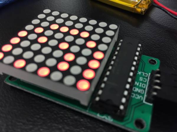
Badgeduino (MAX7219) - Woodford
Summary
Participants will be able to create a wearable brooch with a 8×8 LED Matrix, low resolution display. With the use of an arduino and a battery it allows for an endless possibility of customization and innovation. Furthermore participants can continue work on their wearable tech by adding sensors for even more interesting results.
This is the second part of the wearable workshop, find part one here. It was initially developed for the Flying Arts program ArtizINNOVATE@theEdge in June 2017. This version was developed to reduce the price of the kit for the Woodford Folk Festival 2017/2018.
The workshop will cover:
- Basic Electronic Skills
- Basic understanding of Arduino Microcontrollers
- Basic understanding of Arduino coding and the IDE
- Cross-disciplinary, Arts and Technology
Activity Summary
- What’s wearable technology/wearables?
- Intro to Arduino microcontrollers
- Intro to the Arduino IDE
- Download Libraries and upload them to the Arduino
- Basic / relevant electronic run down of the circuit
- Facilitator and participants put the circuit together, demonstrating step by step and then walking around helping those that need assistance (we’ll do most/all soldering beforehand)
- Run the test script / troubleshoot
- Go through the code and show how to customize the script (maybe demo something that you have made)
- Time for individual work / creativity
- If there is time; show and tell
Materials
| Material | Quantity | Cost | Supplier | |||
|---|---|---|---|---|---|---|
| Arduino Nano v3 | 1 | $3.40 | AliExpress | |||
| Adafruit 8×8 LED Matrix 1.2“ w/ Backpack and I2C | 1 | $2.10 | AliExpress, $2.10 Not tested | |||
| Lithium Ion Polymer Battery - 3.7v 500mAh | 1 | $5.70 | AliExpress, $5.70 | |||
| Micro USB LiPo charger w/ Protection | 1 | $0.8 | AliExpress, $0.45 | |||
| Case | 1 | $4 | In-house | |||
| Attachment / Clip / Lanyard | 1 | $0.22 | AliExpress | |||
| Short USB Cable - USB-A to Micro USB | 1 | $2 | Tronixlabs | |||
| TOTAL: | $10 |
Tools & Equipment
- Computer with working the latest version of Arduino installed.
Instructions
Step Zero: Attaching LED Matrix to Backpack
- Text on LED Matrix facing towards you
- Backpack has a single filled circle, face it towards you (Adafruit logo on your right, filled circle left)
- Insert Matrix into backpack and flip it over
- Make sure that LED Matrix text is on the same side as the “From Adafruit” text on the backpack
- Solder the 16 points and clip off the legs at the base
- Use for header pins and set them into a breadboard with the long pins down
- Put the Matrix and backpack's 4 holes over the pins with the screen facing up
- Solder the pins, do not clip anything off
Step One: Arduino Software and Drivers
If you are using a genuine Arduino with the FT chipsets you won't need to download any drivers on PC and MacOS Sierra or later. If you are using a knockoff Arduino with the CH340G chip you will need to download the drivers for Mac.
Download the latest version of the Arduino IDE. Select your operating system and when prompted choose “Just Download”.
Follow the instruction and install the program on your computer.
Step Two: Connecting and Testing the Arduino Nano
Connect the USB cable to your Arduino. A red and then a green light should light up on the Arduino, indicating that it's receiving power. The green LED should glow solid. Now launch Arduino.
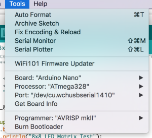
Go to the Tools menu and change the following:
- Board to Arduino Nano
- Processor to ATmega328
- Port to USB/Serial (different depending on OS and Chip)
- If you're having problems finding a USB port you most likely need to download the correct drivers. Once again exact OS (and version) as well as the chip make a big difference.
Once that is done, run “Get Board Info” in the same menu, this should bring up a small popup with some info. As long a you're not receiving an error in the console, you have successfully connected your Arduino!
Another step you can take to test that everything is working is load one of the basic example projects and uploading it to the Arduino.
Go to File → Examples → 01.Basic → Blink
Click on the verify button (Check mark) and let it compile. You should be getting message at the top of the console telling you when it's done (should take no more than a few seconds).
Once that is done, without any errors, click the Upload button (Arrow). This will upload the instructions to the Arduino and it will say “Done Uploading” when everything worked.
Your red LED on the Nano should now be blinking, one second on, one second off. Uploading scripts to your Arduino works! Now we are ready for the real projects.
Step Three: Downloading and opening the project
Below you will find the project files compressed into a .ZIP file. Extract the content wherever you'd like it and open up the wearables_matrix_ino file. The .INO file format should be associated with Arduino if you've installed it. Alternatively you can open Arduino and select the File → Open option in the menu.
Note: You won't be able to run this script unless step four has been completed.
Step Four: Downloading and Installing Library
In order to make the LED display a lot easier to work with we'll need to install a custom version of the MaxMatrix library (found in the download section below).
Go to Sketch → Include Library → Add .ZIP Library
Just find and click the downloaded file and it will be added to your project automatically.
Step Five: Connect the LED Matrix
We're going to connect five jumper leads to the Arduino. Please note that the pins for SCL and SDA are different for each Arduino. Make sure you Google if you are using a different Arduino than in these instructions.
Generally VCC and GND are red and black but to make things a little easier we're letting the wires stick together in their natural order.
Arduino Nano:
- SCL/CLK (System Clock) → D10 (Green)
- DIN(Data In) → D8 (Orange)
- CS (Chip Select) → D9 (Yellow)
- GND (Ground) → GND (Red)
- VCC (Voltage In) → +5V (Brown)
If you've completed the steps in step 3 and 4 you're now ready to upload your script.
Step Six: Battery Pack and USB Charger
Make sure when handling the battery you do not let any conductive surfaces or wires touch. This will short the battery which makes it unusable.
The battery and charger have been prepared but before connecting them to a computer (via USB cable) or the Arduino make sure that the RED wire from the battery is connected to B+ and the BLACK wire is connected to B-. If this is not correct please notify the facilitator immediately, the components will need to be rewired or swapped out. Both the battery and the charging board have protection circuitry but must always be handled with care.
- OUT+ → 3V3
- OUT- → GND (there are two on the board)


