Custom Speaker Stands 2022 Workshop

Developed January 2021 by Andrei Maberley
Acknowledgement
We acknowledge Aboriginal and Torres Strait Islander peoples and their continuing connection to land and as custodians of stories for millennia. We respectfully acknowledge the land on which we all meet today, and pay our respects to elders past, present and emerging.
Summary
In this series of three workshops you’ll work with our team to customize and build our in-house speaker stand design or rolling 19 inch rack, and includes an induction on the Multicam CNC router. Your design will be checked and pre-cut by the Applied Creativity team between workshops two and three so you'll have a single sheet ready for assembly.
Workshop One covers:
- introduction to The Edge Recording Studio and Fabrication Lab
- Customising a parametric model in Fusion360, then exporting files to cut
- Layout of cut files in Vectric Vcarve
- Theortical component of CNC router induction
- Demonstration cut of files
Workshop Two covers
- CNC induction practical component
- Cutting of parts on CNC
Workshop Three covers
- Use of hand tools to prepare CNC cut parts for assembly
- Assembly and finish of speaker stands or rack.
Skills Introduced
- Basic Fusion360 parametric modelling
- Basic Vcarve layout for CNC
- Basic hand tool use
Materials and Files
This is pricing from a local big name hardware store for convenience. Shopping around to specialist suppliers will get better prices.
Materials
Files
Speaker Stands
Rolling Rack
Software and Tools
Software
- Fusion360 (for personal use or full feature trial)
- Vetrics Vcarve Pro (download the trial and use our makerspace key to activate)
Tools
- 4 clamps
- 1 pair cut-proof gloves
- Adjustable spanner (fit m10)
- Sanding block (80 grit)
- Hand power drill
- 3.5mm bit
- Phillips driver bit
- Safety glasses
Preparation
Send an email to participants:
Before the workshop, measure your speakers and listening environment to make sure your speaker stands fit your room, and your speakers fit your stands. Also please create an Autodesk account to access the Fusion360 files online.
You can bring your own laptop if you wish to, but you must install and login to Fusion 360 before you come, as there will not be enough time in the session to do this. You must also bring a mouse with a scroll wheel that clicks in like a button (you can borrow one of ours, so long as you have a USB-A port).
Workshop Walk through
This session Fusion 360
Next session
Last session
Introduction to The Edge
- Fabrication Lab
- Recording Studio
Workshop One
Step Zero: Before we Start
Turn on your Fabrication Lab laptop, log in as 'edgeuser' with the password 'edgeuser' and open Fusion 360.
Step One: Fusion 360
This is a basic introduction to parameters in Fusion360
- Open Fusion 360.
- Click File and save.
Make a Component
In the tool bar click Assemble then Make a component.
- An assembly is an organisation of parts (components).
- Multiple assemblies can be joined together to make a whole product.
Making a Sketch
Click sketch

Select the rectangle tool

then choose a plane to draw on,

and draw a rectangle.

Once the rectangle is complete, it is filled in with a solid colour to indicate it is 'sealed'

Playing With Constraints and Parameters
Constraints are geometric properties that can be used to control your sketch. For a comprehensive explanation check out the wikipedia page.

Delete some restraints from the rectangle.

Then change some parameters, and try to move your shape.
Then click stop sketch when you are done.
Now that you have done some exploring in Fusion, go to file and open a new design for a fresh start.
Measure Your Speakers
Go online and find your speakers and grab the length, width and height.
In your new design click parameters in the tool bar (it can sometimes be under Modify). When the window appears click the little green plus to enter new information.

Then making sure the measurements are set to mm enter the length, width and depth of your speaker into the table one by one. At the end select all the stars to make them all favourites.

Sketching your Speaker
Click assembly, then new component.

Now click sketch, centre point rectangle and the planes will appear. Click the bottom plane.

Begin drawing the rectangle from the origin. Before clicking to creating the rectangle two measurement boxes appear.

In the width box write width and click enter.
Then click tab which will take you to the length box.
In this box type length then click enter and then enter again.
Check that the rectangle cannot move then once done click stop sketch.
Extrusion
Click the rectangle the click create then extrude. A window will come up to the right. In the box next to distance type depth(or whatever you named your speaker depth in parameters). A selection box asking if you want to assign the parameter depth will appear. Click on it then click ok.

Now the we've covered the basics, lets have a look at the speaker stand and rolling rack models.
View the Models online
Fusion360 has a dedicated web gallery that allows us to explore the models in a web browser.
Download the Model and open in Fusion360
Step Through Design History
Use the play button on the design history to check out how the model is made.
Customising the Models
The main constraint we have on customising the models is we are limited to one sheet of plywood per participant. The models in the current state fit onto a single sheet with room to spare.
Modify/Change Parameters
Now you can customise the speaker rack to suite your needs. Enter your changes in the parameter window, the favourite parameters are the easiest ones to change. There are a few points to keep in mind.
- change one parameter at a time, then check the effect on the whole model
- Changes are applied immediately once the parameter is entered
- Click OK to apply all changes
- Use undo to revert (after closing parameter window)
- The only parameter the must be checked and changed if required is the 'material'. This represents the thickness of your sheet of plywood, and ensures we get a tight fit when assembling
- If using the rolling rack model, increase the number of vertical rack units before changing the number of slanted units or the slanted rack angle.
Common Parametric Issues
When changing parameters that affect extruded shapes, fusion360 can 'lose' these shapes when it comes to operations further down the design history. For example in the rolling rack, if the side extrusion is 'missing' a body, then operations using this body, like a combine or mirror will also fail. Confusingly, bodies can be 'missing' and still be visible! The easiest way to fix is to undo the breaking changes, then redo and pay attention to the operations that have errors, which will be marked red on the timeline. Right click on the first operation and edit, note the missing bodies, then reselect the missing bodies and redo the operation by clicking OK.
When using parameters to adjust the numbers inside a patterned sketch, the resulting extruded body may produce unexpected results. For example in the rolling rack model, the ventilation slots on the side of the rack redraw based upon the number of rack units. Lower the number of rack units from ten to five and the extruded body will be correct. Raising the number from five to ten will result in only five slots, as the added slots are selected for extrusion, rather that deselected. To fix this, right click and edit the operation in the design history, making sure no slots are selected for extrusion.
Export sketches as DXFs
Right click on the sketches named DXF in the top level sketches folder in the document tree, and select “save as DXF”
Vectrics Vcarve
Using VCarve Makerspace Client Edition
It is imported to use The Edge makerspace ID if you are using your own laptop - otherwise your designs will not open on the Fabrication Lab machines! To do this open the about menu

And enter The Edge Makerspace ID.
86B4F-F467A-280D9-9F4C6-9C56B-4C528-BEE6F
You will then have to close and relaunch VCarve.
Create a new Vcarve File
1. Click the new file icon or select the New option from the File menu

2. Choose Either a Single Sided Job or Double Sided Job in the Job Type (double sided jobs are ones that you need to turn the material over to make cuts on the other side)

3.The standard Job Sizes are 2400 Width(X) 1200 Height(Y) and 17mm (Z).Ensuring you are using the mm option as your unit of measure. Your material may be different to this, so please measure your sheet before cutting.

4. Set the Zero Position for your job to Machine Bed!!!!!!!!!!!!!!!!!!.

5. Leave the XY Datum Position as the Default. Home is in the bottom left hand corner.

6. When you are happy with all these settings click Ok.

VCarve will then display a 2D workplane, with our vector tools off to the left.

You can always double check these settings in the Edit menu under Job Size and Position

Importing Vectors
Import your vector File by selecting the Import Vector icon in the File Operations Toolbar or select Import Vectors from the File Menu. Use the DXFs we exported earlier from Fusion 360 (or the examples above)

Vcarve will import your vector to the bottom left corner of the Design Window ( zoom out if you can't see it )

Check/Clean Vectors
Now ensure that all the paths that make up the shapes of your job are closed/ joined. Select the Join icon from the Edit Tools Toolbar and select all the paths you want in a shape.

You may need to adjust the tolerance of the Join tool to ensure Vcarve can fill in the gaps between the multiple paths.

Tool fit and Assembly
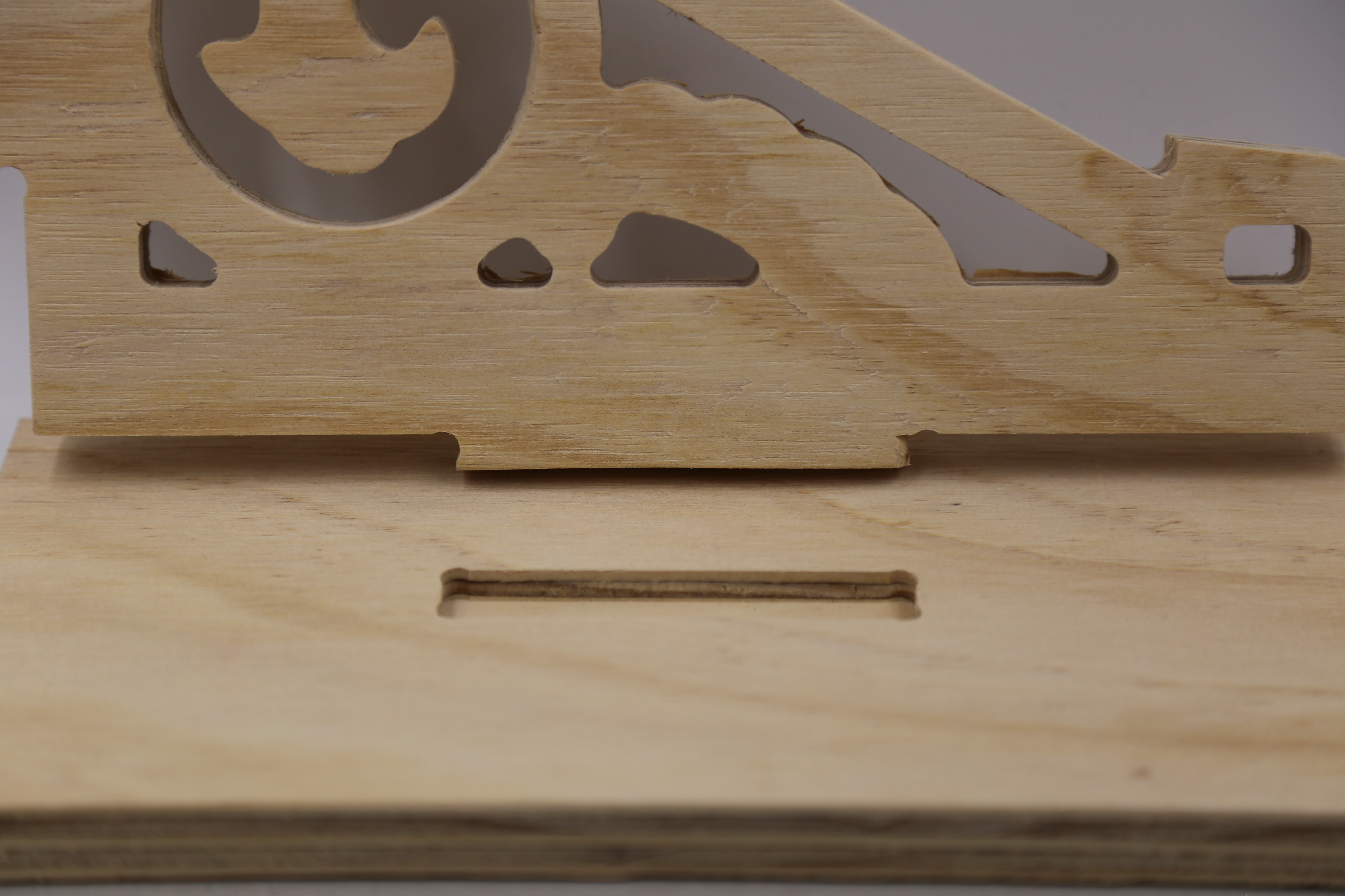
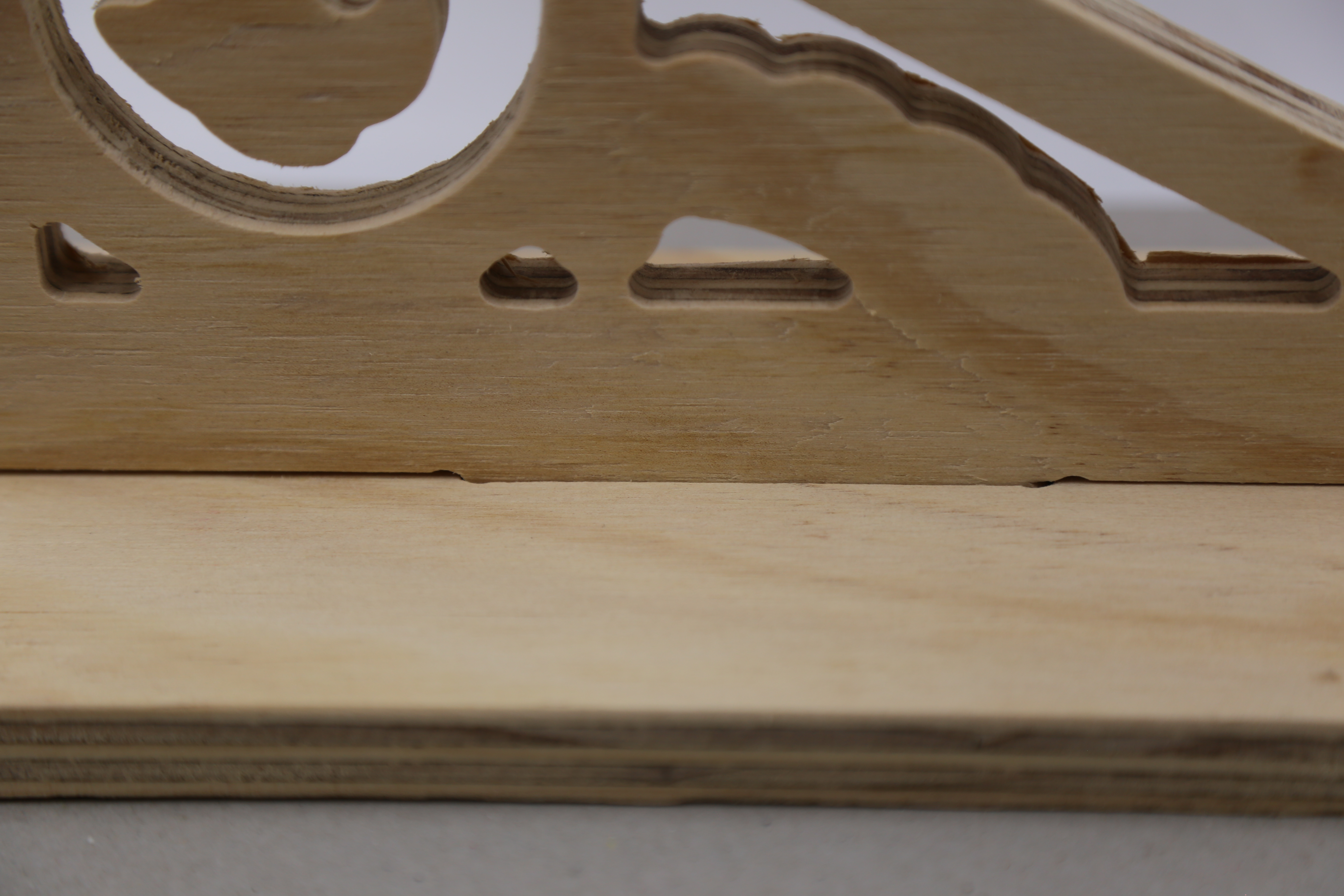
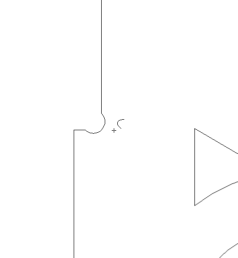
Dogbones
In order for our design to fit together straight of the machine - you may need to use dogbone fillets. This is a small arc on inside corners that fits the tool, and ensure a joint fits to its full length.
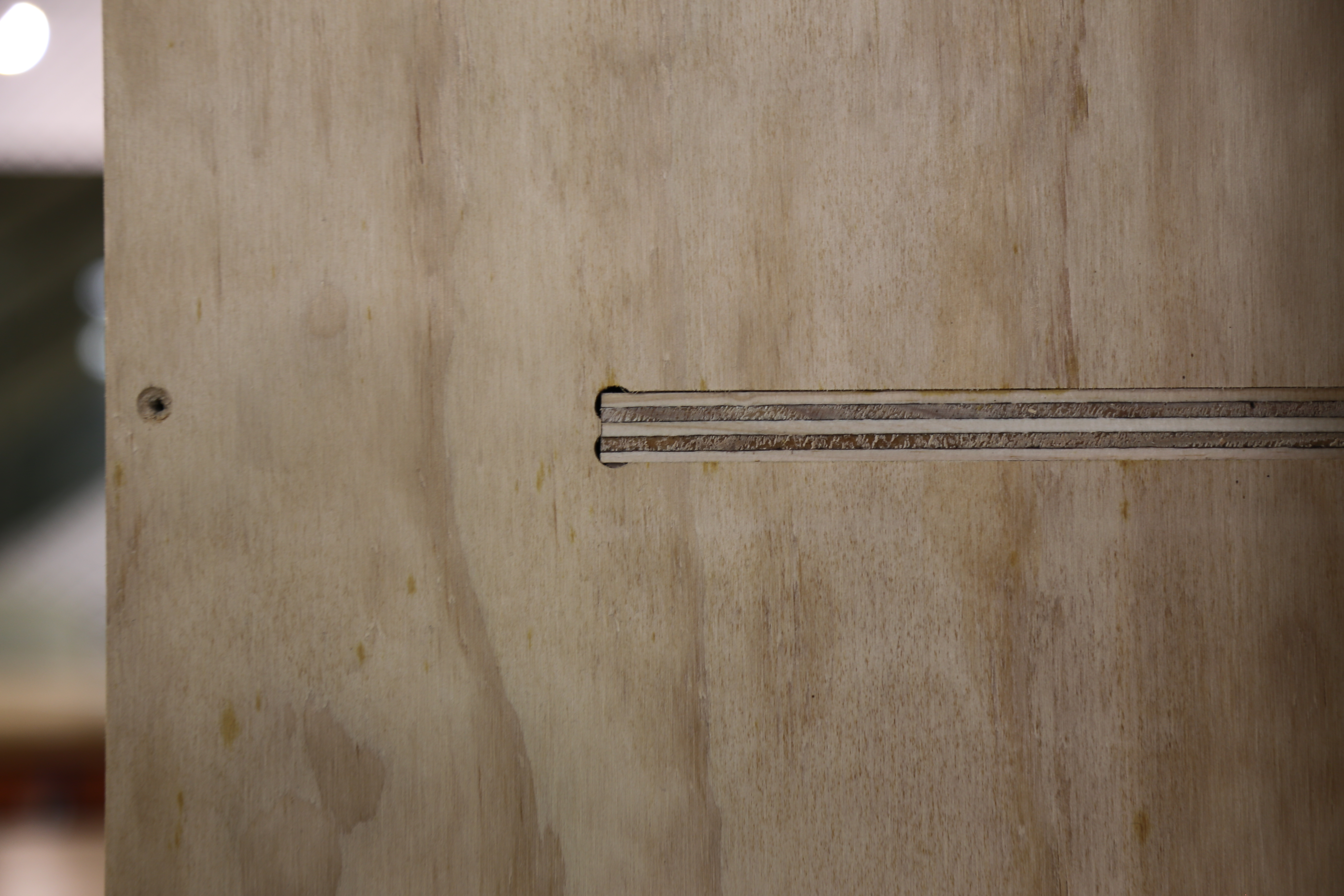
Forr example - to fit into a base, both the fretwork and base will need to be filleted.
Use the fillet tool from the Edit Objects menu
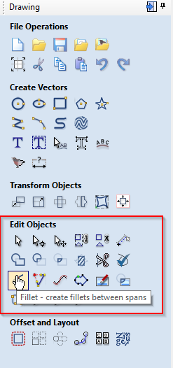
And set the fillet/tool radius to 1/2 your tool diameter, selecting dogbone as the fillet type.
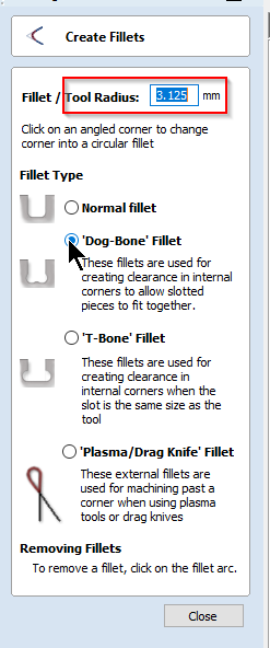
Then hover over an internal corner (you may have to ungroup your shapes first) until the cursor turns into a tick.
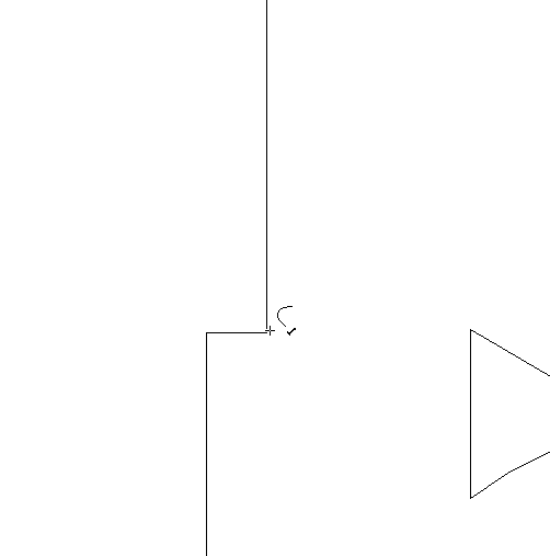
Click to produce a dogbone. If you can't add one - you may need to join your shapes.
Layout
Its time to move and arrange our design on the material - the first step is to group all the shapes so we don't lose our design. Use ctrl-a or drag and select everything, the use Ctrl-g to group (or the group menu button).

Setting up Toolpaths
Toolpaths are the path or route the CNC Router will move the spindle on. The path always follows a vector from your file.
The CNC Router requires more information about the type of tool you are using and how you want to cut/remove material. this is defined in the toolpath menus - found in the top right.

The Edge Vcarve Tool Database
Please use the latest version of The Edge Vcarve tool library. Download, unzip, then merge this into your version of Vcarve

1. Select a shape you want to apply a toolpath to.
2. Pin open the Toolpath Toolbars
3. Check the values in the Material Settings
4. Select one of the 12 types of Tool Operation you would like to apply to the toolpath - in this case
Remember to select the Tool operation order to optimize cut accuracy and minimize the effects of vacuum bed dropoff as parts toolpaths remove material. As a general rule use the following order:
- Drill and engraves and surface level pockets first
- Then cut through pockets, internal cut paths and large parts
- cut external paths small parts last.
Offset and Layout your cutting job
Once you are satisfied that all the required Paths are closed shapes you can layout the multiples parts required to be cut (Eg a 4 legs per stool and 6 stools are to be cut)