Pikelet: a robot that talks scratch

Developed by Peter Musk as part of a fee-for-service project for Brisbane Catholic Education during 2016.
The brief was to develop physical resources suitable for use in a school context that would assist in teaching coding and robotics. The target audience was P -12 students.
After a survey of the commercially available hardware (summary here: robotics_and_coding_platforms.docx), and considering our own experience of working in school environments, key barriers to wide adoption were identified:
- cost - most commercial platforms were >$200 each, and many were much more. This makes the use of multiple platforms in a single class prohibitively expensive for most schools
- closed source software - many existing models use copyrighted and unmodifiable software. This reduces the potential for student initiative, and is therefore a barrier to learning commonly used coding languages
- scary hardware - many platforms were developed for a hobbyist market, confronting users with loose wires or bare circuit boards and requiring skills and tools to assemble that are not common in schools
- low ceilings - products targeted at an educational market tended to have a narrow (though often well-developed) utility. They might do one thing very well, but were not useful across a range of ages and abilities
- technology focus - while the investigation of robotics is well advanced in High School Technology classes, not many platforms had applicability across other subject areas, and this made them less useful in Primary settings, which use an integrated curriculum approach
Our response has been to develop the Pikelet - a robotic platform based on a Raspberry Pi 2B, with additional hardware to provide sensor capability and motor control. Software has been built on Scratch GPIO (which is a derivative of Scratch 1.4), that combines the Scratch browser based block-coding environment already widely used in Queensland schools with new blocks to receive data from an increased range of sensors, and to control motors and servos. These modifications (and future student-led adaptations) are coded in Python, providing a pathway to using this device for teaching higher level coding languages.
Summary
Hardware
Device
The Pikelet project has been developed with two distinct hardware modules in mind:
- a mobile device (a two wheeled vehicle), and
- a stationary device
The two modules will work together to provide both a programmable and responsive mobile agent, and a programmable and responsive environment controlled by the stationary device. This allows for creatively competitive interaction between groups of users coding the active environment, and those using the robot to explore it. The opportunity for surprise and hidden triggers being built into the environment is intended to motivate those operating the mobile device to develop coded solutions on the fly, or in a turn-based sequence. Having the ability to make the environment active also allows for greater creativity in design, and broadens the possible curriculum applications.
Both forms contain the same processing unit: a Raspberry Pi 2b with a custom added printed circuit board (a PCB, also called a 'hat') that has sockets for sensors and motor controls. These electronic components are enclosed in a 3-D printed case which can be attached to a mount on the mobile device. The case has a clear acrylic top layer to allow users to see, but not to touch, the electronics, and which has holes to take the plugs which end the sensor cables. Sockets are provided for
- up to 6 digital sensors (including one I2C for the accelerometer), which also serve as output sockets for servos, LEDS or other low current devices
- one SPI
- one for UART (for the RFID sensor)
- one for analogue input (for the sound sensor)
- two motor (high current output) connections
Sockets and plugs have been chosen to be suitable for inexperienced users, and are large and self-orienting. The sensors supplied are fitted to 200mm flexible cables and soldered plugs. The power connectors, similarly, are robust (DC barrel jack for the hat) and familiar (mini USB for the Raspberry Pi).
Design throughout has been guided by the need to protect electronic components from accidental damage, as well as creating an impression of safety and accessibility for the (non-expert) user. Simple quarter-turn connectors have been developed to join the parts of the case together, to allow easy access for any necessary troubleshooting or repairs (no tools are required for disassembly), and these connectors are large enough for use by children with developing dexterity.
Power is supplied via a readily available rechargeable power bank (such as used for mobile phones), which offers familiarity, ease of use and extended operating life. The goal was to produce a system which could operate for a whole school day without needing recharging, but this is always dependent on use.
Environment
To help make it easy to wire sensors and other devices into the programmable environment, a system of hollow, connectable floor tiles has been made. The tiles are 210mm square (to allow fitting of a sheet of A4 paper on top that can be decorated appropriately), with acrylic tops and bottoms, and a 12mm space in the middle. Ports in the sides allow hidden wires to run between the tiles, and simple 6mm square connectors help join and hold them in place.
Each assembly is held together by quarter-turn 3D printed connectors in each corner, that can be undone with fingers, or a coin (no tools required).
Connectivity
The package supplied to schools comes with a WiFi router that plugs into a standard wall power socket. The Raspberry Pi 2b can take a USB WiFi dongle, and together these mean the Pikelet can operate on its own independent network. This configuration avoids issues with connecting external devices to closed (school) networks, and allows student devices (laptops or tablets) to connect directly to the Pikelet, and thus allows for programming on the fly by users. The default visual environment is the familiar Scratch dashboard.
As a further option, the Pikelet can be supplied with a cheap, Android tablet, which further reduces any barriers to operation.
Later models of the Raspberry Pi with onboard WiFi capability were not used, because these natively run a version of Scratch incompatible with Scratch GPIO.
Software
The Pikelet is controlled by sequences of block code, written in an extended version of Scratch that is included on the device. Cunning use can produce a fairly autonomous device, but as described below, this might not suit all desired applications.
New Python scripts have been written to add the ability for the device to respond to data from the following sensors:
- light - which can be used to develop a line-following program
- sound - basically a microphone, allowing responsiveness to noises
- distance - an ultrasonic sensor for obstacle avoidance
- accelerometer - adding vibration sensitivity and motion detection
- RFID - recording the presence of individual RFID chips placed in the environment, by returning the specific identification code of each chip
Additionally, the model code which forms the basis for each of these innovations is included in the documentation, as a guide to further development and experimentation by students.
Curriculum
The Pikelet has been developed to facilitate use across all subject areas, and by a range of students from about Yr5 onwards. Younger students require a different approach to learning coding, and a physical coding activity is given in the Yr2 example below. The Yr3 example could be used to bridge the physical to screen based environment, but can also be used with the Pikelet if Scratch is introduced.
The documents below provide lesson plans for the sort of curriculum related activities that could be undertaken, with references to the Australian National Curriculum.
The following tutorials are good for beginning Scratch with students:
Instructions
Networking
Connecting to the Pikelet can be either by
- cable (through the ethernet port on the Raspberry Pi), or
- over a WiFi network (through the WiFi dongle you have inserted into one of the USB ports on the Raspberry Pi).
You can also connect a screen, keyboard and mouse directly to the Pikelet by using the USB and HDMI ports provided on the Raspberry Pi (for example, if a facilitator wanted to develop and save pre-written code as a starting point for the activity).
Pikelet WiFi
The Pikelet is supplied with a stand-alone WiFi router, already configured for the Pikelet, so as to provide a network independent of institutional constraints. This mode allows maximum flexibility for driving the system and coding on the fly without trailing cables around the workspace.
The Pikelet software will look for a network called Pikelet_01 and connect automatically when it is switched on.
The router supplied has been set up with the following characteristics:
user:  root \\
password:  pikelet\\
 WPA-SSID:  Pikelet_01 \\
 security:  WPA PSK \\
 key:  Pikelet_01
The Pikelet is automatically assigned a static IP address of 192.168.1.184 by the router.
Setting up a new router
Any new router will need to be configured with the details above. We recommend using a router that can run OpenWrt, an open-source firmware that runs on many consumer routers.
Connecting to the Pikelet over WiFi
The Pikelet has a VNC server installed (it loads on start up) to allow WiFi access by another device (tablet, laptop etc). You will need to install a VNC client on your access device to see the screen running on the Pikelet, and to write and run Scratch code remotely. (The following instructions were developed for TightVNC software, available free from http://www.tightvnc.com/download.php ).
When you have downloaded and installed the TightVNC client software, use the following to connect to the Pikelet:
VNC host: : 192.168.1.184:1 (note single colon only is required)\\
password: qwerty \\
Connection is confirmed when you see the Pikelet start screen, which looks like this:

Connecting a sensor
Step 1: Start Scratch
Double click on the Scratch icon on the start screen, and the familiar Scratch workspace will appear.

Step 2: Start the Python server
Because the code that allows Scratch to see and use sensor data is written in the Python language, you need to start a program that can allow this to happen.
Double click on the 'Start Server' icon (below the Scratch cat), and a new menu will appear - click on 'Execute' to start the Python server.

![]()
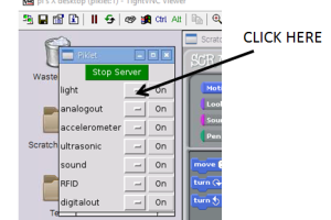
Now a pop-up appears with buttons for the server, and for different sensor types. Click the 'Run Server' button, and it will turn green to show the server is on.

![]()

Step 3: Enable the sensors
Now you need to tell Scratch to be ready for input from the sensors you will attach to the Pikelet. This is done from the Sensors menu in Scratch.
At the bottom of the list of Sensor blocks, RIGHT click on either of the blocks below the faint line, and a pop-up will appear. Click on 'enable remote sensor connections'.

![]()
Step 4: Connect to the Pikelet
A new pop-up appears, telling you the Pikelet is connected to Scratch. You MUST click 'OK', or the sensors will not work (when you do this, the pop-up disappears).

![]()
Step 5: Activating the sensor
Sensors are attached to the Pikelet by plugging them in to the correct socket on the top of the device. Not every socket can work with every sensor, and a diagram detailing the layout is below (more details in this file:
piklet_hardware_documentation_v2.docx )

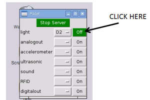
For ease of use, the buttons in the sensor control pop-up have a drop down menu which lists the correct sockets for each type of sensor, so all you need do is:
- decide what sensor you want to attach
- click on the first button to the right
- select a socket from the drop down menu that will appear

- plug your sensor into that socket
- now turn the sensor on, by clicking the 'On' button, which will turn green
Using a Sensor with Scratch
Now that your sensor is connected, and working, you can use Scratch blocks to display the data, or use it as a trigger for other actions.
The Python code will automatically give options in the Scratch blocks that relate to the sensor you have installed. The steps that follow show one simple way to make the data visible, by linking it to a sprite.
Step 1: Set up a Control method
The Pikelet reads each sensor many times a second (every 50 milliseconds), records the value and then broadcasts a message in Scratch that the value has been updated. This update is the key to controlling how the data is used.
Because the broadcast happens automatically (no green flag is required), the simplest control method is to begin by dragging the 'When I receive' block onto the workspace.
Click on the arrow, and you should see an option relating to your sensor (in this case 'light updated' ). Insert it in the block.
If you do not see an 'updated' choice for the sensor you want to use, then something has gone wrong in the set up, and you will need to go back and check that the sensor has been attached correctly.

Step 2: Set up the visualization
A simple way to see the values being recorded is to have the sprite 'say' it.
Go to the Sensing panel, and drag the 'sensor value' block onto the workspace.
'Slider' is the default, but when you click on the arrow, a menu appears with the new sensor available (choose the one closest to the bottom if it appears more than once).

Now go to the Looks panel, and drag the 'say' block onto the workspace.

Drag the sensor value block into the say block, and the sprite will begin to 'say' the sensor reading on the screen (many times a second).

Step 3: Setting up other outputs
While visualizing the sensor output through a sprite is an easy way to check everything is working, it may be more useful to use sensor data as an input to other actions (like turning on the motors or running a prepared set of instructions when a threshold is reached).
This can be done using the other Control blocks in Scratch, and linking or looping just as you would to control the movement of a sprite on the screen.
Step 4: Setting a threshold
You can set a threshold value for displaying changes in sensor data so that the value does not automatically change every 50 ms. The threshold is the difference between one sensor reading and the next which must be exceeded for an updated value to be recorded.
Make a Threshold variable
Begin by going to the 'variables' window, and select 'Make a new variable'. A pop-up appears asking for a name for the new variable.

Name the threshold
You must use a standard syntax to name this threshold variable: piklet_<sensor name>_<sensor socket>_threshold . (Note the spelling of piklet, necessary for the code to recognize the change).
This can be seen in the example below, for a light sensor plugged in to socket D2:

Set the threshold value
Now you can use this new variable to set your threshold.
First, go to the 'Variables' window, and you will see a new set of options for the variable you just made.
Drag the 'Set ' block onto the workspace, and edit the default value of 0 to whatever you have chosen (in this case, 0.5).

Now a new value for the 'light' variable will only be shown if it is more than 0.5 units different to the current value.
Use the threshold
You can use this threshold by dragging it into a control script as seen below:

Now the sprite will only say a new value for the light sensor if it is more than 2 units different to the current value.
Controlling the Motors
Step 1: Select the motor socket
As for a sensor, first turn on the Pikelet, and the Python server. You also need to enable remote sensing from the Sensors window as before (and click OK when the Piklet connected to Scratch pop up appears).
In the Python server drop down menu, select motor1, and a list of possible connections appears:

Select either ML (left wheel) or MR (right wheel) - the others are not yet active

Step 2: Turn on the socket
Now click the on/off button in the drop down menu to activate the socket you have chosen.
(It will turn green when on, as before)

Step 3: Create the motor variables
You will need to create two variables to use this motor - choose 'Make a variable' from the variables window
First, make a variable named piklet_motor_ML_enabled to make the motor available to Scratch:

Remember, your script must set the “enabled' variable to 1 to make it active
Then, make another variable named piklet_motor_ML_speed to allow you to control the speed:

Speed can be set between -100 and 100. Negative speeds make the motor go in reverse.
Step 4: Set up controls
Now you can use these variables in a Scratch script to control the motor - in the example below,
- a Green Flag block controls when the motor is activated
- the 'motor enabled' variable is set to 1 (which turns the motor on)
- the 'motor speed' variable is set to 30 (a range from -100 to +100 is possible)
- the wait block limits the time the motor is active
- the final 'motor speed' variable turns the motor off

This script will make the Pikelet turn in a circle (since only one motor is on)
Trouble shooting
Physically connecting motors to the Pikelet
Each motor socket on the Pikelet board has 4 pins, and each motor has two wires - one red, and one black.
Physical connection is to the two OUTSIDE pins in each motor socket, according to the diagram below:

If you attach motors back to front, then you will see them operate in reverse, or some other unexpected way. You cannot damage them by doing this, but will need to write your scripts accordingly.
Speed settings
The motor speeds should be set between -100 and 100. If you go outside these boundaries, then the Pikelet software will ignore any other values, and may not work.
Controlling other physical outputs (LEDs, servos, etc)
Scratch GPIO allows you to use the GPIO pins on the Raspberry Pi to power external devices, using the methods described here:https://www.raspberrypi.org/documentation/usage/scratch/gpio/README.md.
More examples (and lesson plans) can be found here: https://pihw.wordpress.com/lessons/rgb-led-lessons/rgb-led-lesson-2-scratch-gpio-getting-started/.
In order to do this, you will need to use the pinout plan below for the hat used on the Pikelet (which details which GPIO pins are available at each of the sockets on the hat). You will also need to construct a cable which can connect the socket to your device.

Production Notes
Raspberry Pi Case
Case Design
To protect the electronic components, and to reduce user anxiety, it was decided to enclose the Raspberry Pi and hat in a 3D printed case.
The design was developed from this existing publicly available model:

This initial design was modified
- to include an extended upper case that covers the hat board
- to include a clear acrylic top (attached with trapped nuts) that has holes to allow access to the sensor sockets on the hat
- by adding extra ventilation slots to the bottom of the case, and
- using quarter-turn joiners rather than screws to connect the layers
All design files for 3D printing the case parts and joiners, as well as a 2D cutfile for the top cover (with holes) are here:
Case assembly
Step 1
Locate the case bottom. You will see that it has two lower connector slots (to attach to the support) and top upper slots (to attach to the top of the case)


Step 2
Insert the Raspberry pi (with hat attached) into the bottom case, matching the slot provided to the SD card socket


Step 3
Locate the case top and clear acrylic lid. Insert M3 nuts into the 4 nut traps in the case top before placing the lid on, and attaching with 12mm M3 screws.
Check that the orientation of the holes in the lid matches the layout of the blue sockets in the hat before fixing in place


Step 4
Locate two connectors, and insert them into the upper slots. Turn to fix the case halves together.
The halves should align so that sockets to connect the Raspberry pi to HDMI and USB2 are open.


Pikelet chassis
Support design
The Pikelet was built on an existing robotic platform, now discontinued, but originally sold by Sparkfun (https://www.sparkfun.com/products/retired/10825). Design files for the baseplate used are here:
A mounting platform to take the Pikelet case, attached using the new connectors was also devised. Design file is here:
pi_tin_support_v10_transverse.stl
This support platform has holes to take the shell hinges, and is raised to allow a power bank to be located underneath.
Support Assembly
Step 1
The support has holes for connectors to attach the case, and 3mm holes in the feet for attaching to the baseplate with 12mm M3 screws.
It is easier to attach nuts to these screws from the underside. The curved sides face the front, and arch over the wheels


Step 2
Places the case on the support (only the bottom is shown) and insert two connectors in the aligning holes. Turn to fix in place.
(It is easier to have the support screwed onto the baseplate before adding the case containing the Pikelet, and the view shown is to make for easier understanding)


Pikelet shell
Shell design
A shell to cover the case and support was designed by Holly Pepper, and 3D printed from the following file (print time was about 7hr, and a larger format (300mm square) bed is required).
pikelet_shell_v8_offset_hinges_complete.stl
This design requires the following hinges which screw on to the support, and the shell with 10mm M3 bolts. The hinges have a curved side which matches the inner curve of the shell.
pikelet_shell_v8_offset_hinges.stl
This shell has slots down either side to allow sensor cables to emerge, and is intended to be covered with student devised artwork to represent whatever role the Pikelet is playing (eg: a ship, an animal, a vehicle etc). Adding velcro dots to the outer shell could assist this.
Pikelet landscape tiles
Hollow tiles were devised to allow for sensor and actuator placement throughout the landscape traversed by the Pikelet. They are designed so that the largest square possible from an A4 sheet of paper can be attached to the top (held in place by the corner connectors), to allow temporary topography to be drawn over the tiles. These were fabricated from 3mm (top and bottom) and 6mm (sides) acrylic, according to the designs in the files below:
bce_pikelet_tiles.zip
Quarter turn connectors at each corner were designed and 3D printed, according to the files here: pikelet_board_connector_185_x_6mm_shaft.zip.
Note that a 3mm shaft for these connectors was tried and found to be too fragile for use.
Costings and Suppliers
The following spreadsheet lists suppliers and costings for this project: costing_and_suppliers.xlsx
PCB design files
Here are the design files for the version of the hat used in this project:
w21644asc2_raspberrypi-hat-piklet---v2.2.zip
Note that there may be a missing connection between a couple of points, which was repaired by soldering a wire in place.