Large Signage
This page documents the process of making large physical signage using the CNC Router.
Rationale
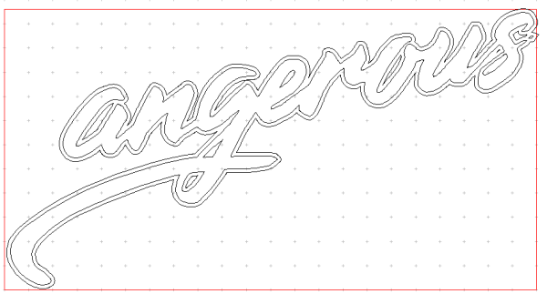
As events are programmed offsite, the need for physical signage more appropriate than a pop-up banner has been realised. For example Dangerous Fridays will be presented offsite, as will One Last Apocolypse.
Use Case
For the Dangerous Fridays event, Daniel has envisioned a large logo, to be lit with low power 12DC lamps, made as large as feasible on the CNC router. It needs to be light enough to be hand transported if need be, but still have a professional level of finish.
Design Process
The concept is a lightweight, approx 2400mm x 2400mm foam structure, 100mm deep made of two layers of foam glued together, sanded then laquered. Talia Yat has designed the logo, which has been simplifed slighty first by Daniel, then myself.
Prototype One
The first prototype was cut on friday the 23rd June.
Design Prep
Ive have taken Talia's file, exported it from Illustrator as a DXF (latest version) then cleaned it up in Corel Draw. We need to do this because the original (illustrator) file is full of overlaps and un-cuttable shapes. Next I usually make a 3D model in Fusion360 to test the shapes, but the detail in the curves broke fusion360 so I skipped this step.
The cleaning process is;
- Convert object to Curves
- Remove fill and set line to hairline (black)
- Join all lines with a 'extend' and a tolerance of 0.
- Manually edit curves to remove sharp corners and join still unjoined lines.
- Combine all curves.
- Save and export as DX using AutoCAD 2008-2013 with units as mm.

Test Curves with Pen
The next step is to make sure Enroute is seeing the DXF with the right units and as nice smooth curves. A test with the pen tool is convenient for this as it doesn't spin up the spindle.
* Import DXF into enroute
* Make an engrave path with the pen tool
* Test on CNC router.
What we are looking for a nice smooth curves, not a series of straight lines.
7
Make Offsets (Contours)
We'll Corel to make the offsets required to cut the line width that we need. We are looking for a minimum thickness of 15mm. The Contour tool in Corel makes this easy.

Once applied our shapes look like this.

Don't worry about arranging the shapes here - we will do this in Enroute, just export your DXFs again, using the same settings.
Cut Prep in Enroute
Now we need to import, layout and make our toolpaths.
- Do a new document, then use the 50mm foam plate preset.
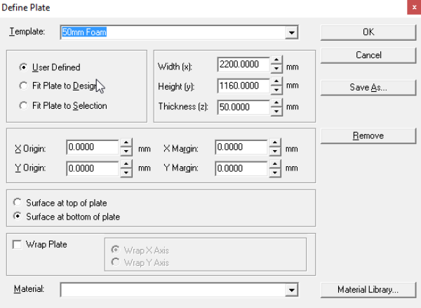
- Import your DXFs. NOT AS LEGACY
- Group your letters and shapes NOW so you can move them around without getting them out of alignment.
- Try fit parts onto the plate.
- Fail. (the actual material size is smaller than the 2400 by 1200 the sign was designed for)
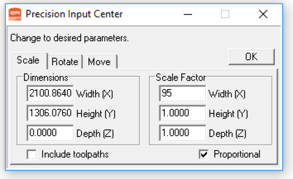
- Resize all parts using the 'precision input centre' (F2) to .95 of original proportions.(do a quick calculation to see if we've stuffed our line thickness…15 * .95 = 14.35.. should be fine)


Tool Paths
Because the foam is so soft and we have a dedicated bit (T5 - 6.35mm Foam cutter), we can crank through it really quickly. I've started at 6000 mm/min and 3 passes + 2000 mm/min finish and worked up. The final settings are:
- Routing 2 pass
- 8000 mm/min 48mm depth, then 2000 mm/min finish
- Fills 2 pass
- 8000 mm/min
Prototype One 'The D'
The'D' the prototype cut, sanded glued and lit.
Revision A
The first revision requested by Daniel is adding the holes for lights at 15cm intervals with a diameter of 50mm. This requires a line traced in the middle of the letters, then individual routed holes. This is best done before applying contours.
I've found two methods for this - one is manual, the second uses an autro-trace function that finds a centreline in a bitmap image. Lets do this is corel.
First we convert to a bitmap.
- make a copy of the shapes layer
- remove the contours
- right click on contour line and 'break contour apart'
- select contour and delete
- Fill all ojects with black (Use Object Properties)
- Convert to bitmap (Bitmap - Convert to Bitmap)
- Trace Centreline (Binmap - Centreline Trace)
- Manually clean up
- Delete jagged nodeds
- break paths to smaller segements (no loops)
- Export as DXF (using above settings)
Revision B
Daniel requested a change to the design, with a 30mm pocket inset into the bottom layer. This required nesting of paths in enroute. The most straight forward way to do this is to use separate layers, with paths exports a layer at a time.
This cut process resulted in difficult to transport and align shapes.
The Coke Sign
At this point attention was shifted to making a Sign for GU music theatre production. The sign was cut using Prototype One, Rev B method.
Prototype Three -- Dangerous Fridays Version 2--
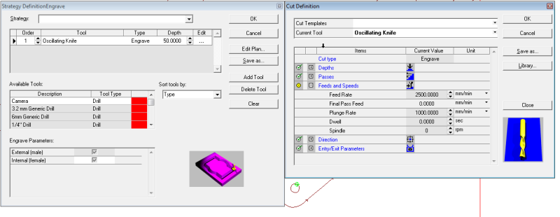
With the installation of the reciprocating knife for the Multicam CNC Router, and the on-lining of Vcarve for cutting, its time for prototype three.
This prototype is intended to use the knife for two layers of foam, with a routed 5mm mdf layer in-between to add support. We will make the knife paths in Enroute, then switch to vcarve for the router.
Talia has redone the illustrator file with thicker lines and added holes for the lights.

Design Prep
As with Prototype One - we need to clean up stray lines. To work on the knife we will also have to remove any curves with a radius less that 5mm, smaller curves may break the blade.
Clean Up
Loading up the AI file in Corel Here we can see a fee jagged curves and some left over vectors - this is the kind of stuff that needs to go.

lets turn of the fill and make the lines hairline to see whats going on.

Manually deleting the loops and smoothing out the vectors gives us something like this. To make this easier - ungroup all the object and break apart the curves.

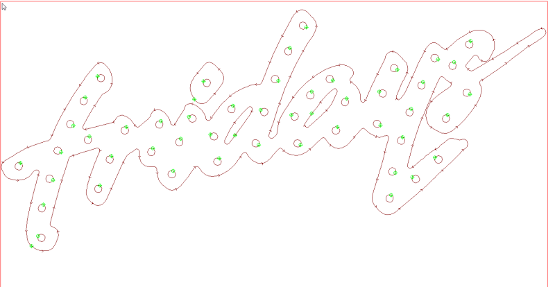
When its all cleaned up this is our design.

Next is time to remove any small curves - Pull up the Fill/Scallop/Chamfer docker. The Multicam guys say 5mm radius is fine - but I'm going to set 10 mm 'cause I ain't breaking the knife.

Select a shape, then apply - then undo straight away and you'll get a nice little preview of what the fillet has done outlined in blue.

If you get this error, then you have a sneaky little vector in there, find it and delete it.

Our final cleaned and filleted file looks like this - notice the hard corners on the dashes above and below the words are still sharp - I din't fillet them.

Now lets get the globe holes ready. We need to get rid of the red outlines, these are just guides to make sure the globes fit. First select a red outline in the object manager.

Then lets use corels 'find and replace' function to find the specific object.

We will use our current selection as the start of our search

Corel will grab the info from that object….

Now we can 'find all' matching objects

Because the matching objects are all in groups Corel asks if we want to ungroup them - yes we do…

To double check you've got the right objects - check in the object manager.

Now delete - and the cleaned up globes looks like this.

Contours
Now its time to add contours as described in prototype One. A few tips on this process:
Move the shapes around so the contours don't overlap, but make sure you move the globe outlines too!!
Break apart the contours

Used the 'weld' tool to join together a couple of contours where they overlap.

Where this weld has resulted in a sharp corner, I've filleted again to smooth it out.

To make the next stage easier - group all the words and bulbs together, and give them separte, clearly named layers.

This final corel file looks like this.

Cutting - 70mm Foam
Using the knife speeds up the cutting process, even though the feed rate is slower (3000 mm/min) the clean, precise cuts leave no powdered waste to be cleaned up.
Layout
There are two foam jobs per sheet, organised in Enroute as separate layers. There is only one type of path -engrave- available with the knife. The settings used were feed of 2500 and plunge of 1500. These are conservative, it would be good to go faster I think.
For example the first layer of the 'friday' looks like this, with holes for the globes and an external profile.
Routing - 6mm mdf
This process was successful using external routes and a pocket to clear the light sockets. I tested using an engrave path for the outline and internal offset for the sockets but this left the shapes a little loose in the foam.
However using MDF means we have to change from the oscillating knife to router head to complete the job. I proposed we cut the inner layer (layer2) out of card with the knife - requiring a knife change only.
Prototype Four = Wonderland


Prototype Five - Coke V2
Resources
A zip containing all the files used for Dangerous Fridays prototyping.
dangerous_fridays_bra_865941.zip
