~~REVEAL~~
Deskduino
Summary
Participants will create an electronic display for their workplace/desk. The display uses a programmable 8×8 LED Matrix display, an Arduino Nano and a cardboard frame made using a laser-cutter.
Skills Introduced
- High level overview of circuit and components
- Case assembly and wiring between components
- Coding in the Arduino IDE
Materials
Electronics
| Material | Quantity | Cost | Supplier |
|---|---|---|---|
| Arduino Nano v3 | 1 | $3.40 | AliExpress |
| MAX7219-dot-matrix-module | 1 | $2.10 | AliExpress |
| Short USB Cable - USB-A to Micro USB | 1 | $2 | Tronixlabs |
| Total | $7.50 |
Frame
Tools and Prepartion
Tools
- Computer with working USB 2.0 ports
- A working internet connection (or pre-downloaded files)
- Pen/Awl
- Ruler
Introduction to Arduino Microcontrollers
What is a micro controller?
A microcontroller (or MCU for microcontroller unit) is a small computer on a single integrated circuit.
- one or more CPUs (processor cores)
- memory
- programmable input/output peripherals
- can be mixed signal devices interacting with
- digital signals
- analog singals
Why use an MCU?
Microcontrollers are small, low powered and robust, making them perfect for embedded systems such as:
- medical devices
- remote controls
- office machines
- appliances
- power tools
- toys
- wearables!
What is Arduino?
Arduino is an open source computer hardware and software company, project, and user community 1) .
- The hardware is based on the Amtel 8-bit AVR MCU
- The software uses the Processing IDE, with a simplified version of the C++ language
- Open source has led to the creation of a huge range of
- clones
- compatible devices
- peripherals
- A strong community means
- “Someone, Somewhere has solved the problem”
- we can run this workshop using and adapting existing resources.
Assembly and Testing
It's time to get started!
Step One: Connecting and Testing the Arduino Nano
Download the Arduino IDE
Download the latest version of the Arduino IDE.
Follow the instruction and install the program on your computer.
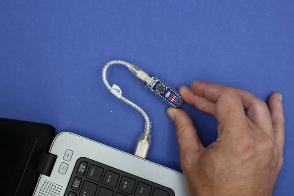
Connect Your Arduino
A red and then a green LED will light up on the Arduino, indicating that it's receiving power (for some Arduinos this may just be a single red light)
Now launch Arduino IDE

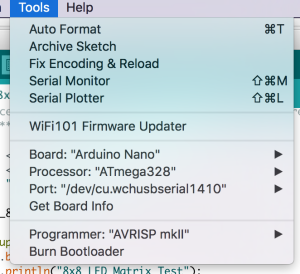
Go to the Tools menu and change the following:
- Board to Arduino Nano

- Processor to ATmega328

- Port to USB/Serial (different depending on OS and Chip)
- If you are having problems finding a USB port you most likely need to download the correct drivers.
Once that is done, run “Get Board Info” in the same menu, this should bring up a small pop-up with some information.
As long a you're not receiving an error in the console, you have successfully connected your Arduino!
Test with the Blink Example
Another step you can take to test that everything is working is to load one of the basic example projects and upload it to the Arduino.
- Go to File → Examples → 01.Basic → Blink
- Click on the verify button (Check mark) and let it compile. You should get a message at the top of the console telling you when it's done (this should take no more than a few seconds)
- Once this is done, without any errors, click the Upload button (Arrow)
- This will upload the instructions to the Arduino and it will say “Done Uploading” when everything worked
- Your red LED on the Nano should now be blinking, one second on, one second off
- Uploading scripts to your Arduino works!
Step Two: Assembly
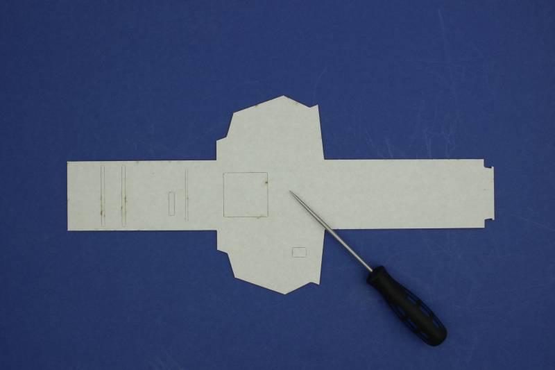
When working with the cardboard frame make sure you take care not to accidentally bend it other than where we have bend lines as this may affect the structural integrity later on.
If your frame has any holes filled in, make sure you remove them. Using an awl or pen/pencil works well but your hands should be sufficient.
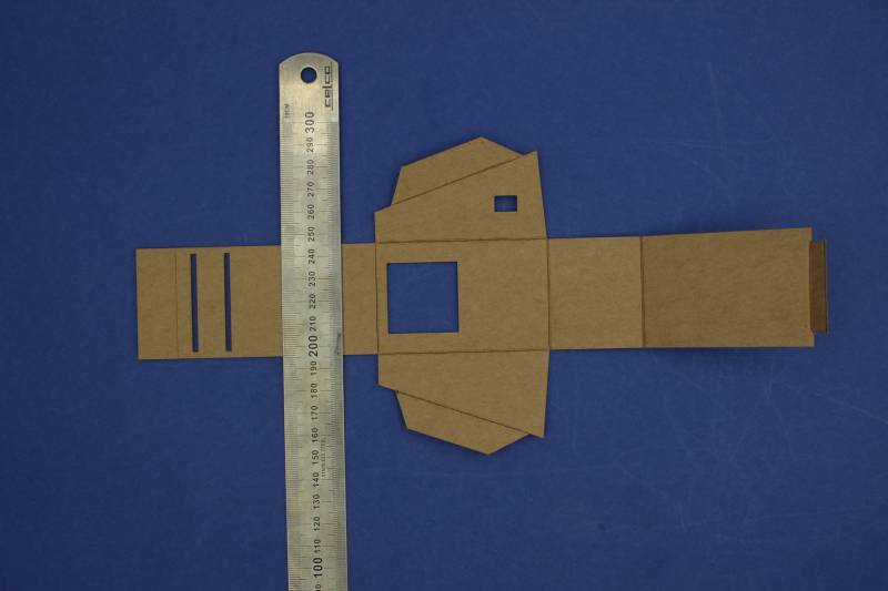
Flip the frame so that the natural side faces up. We are now going to start shaping the frame using the bend lines
Let's fold it together. Don't slot the tab in yet as it will be difficult to open up again and may end up damaging the frame
Step Three - Assembling the Electronics
Now it's time to mount and connect the screen.
Mount the screen
Write down what color wire goes to each of the pins (each pin is labeled). This will make it a lot easier to correctly connect the screen to the Arduino later
Slot the wires through the dedicated hole. Try to run the wires on one side of the screen to help make everything fit
Connect the screen
The Arduino fits into the two parallel slots. Make sure you orient the USB connector to match with the slot in the frame
Fold the side of the frame over (with the Arduino still attached) and connect the wires to the correct pins. This is where the notes you took earlier will come in handy. The pins on the Arduino are also labeled.
This is how the wires need to be connected:
- SCL/CLK (System Clock) → D10
- DIN(Data In) → D8
- CS (Chip Select) → D9
- GND (Ground) → GND
- VCC (Voltage) → 3V3
Close it all up
Step Four - Using the Library and Project
Now it's time to check our Arduino and LED are talking to each other.
Download and install the Library
In order to make the LED display a lot easier to work with we'll need to install a custom version of the MaxMatrix library (found in the download section below).
- Go to Sketch → Include Library → Add .ZIP Library
- Just find and click the downloaded file and it will be added to your project automatically
Download and open the project
Below you will find the project files compressed into a .ZIP file.
- Extract the content wherever you'd like it and open up the wearables_matrix_ino file
- The .INO file format should be associated with Arduino and launch it automatically
- Alternatively you can open Arduino and select the File → Open option in the menu
Note: You won't be able to run this script unless you have downloaded the library above.
Upload the Project
It is time to test the project file in your desk Arduino. Upload it the same way as the blink file. Your desk Arduino should say Free Bear Hugs.
Hacking the Code
While it's beyond the scope of this workshop to teach your how to program your Arduino - here are some tips on:
- Changing the displayed text
- Displaying a symbol
- Changing the speed of the text scrolling
void loop()
{
 // displayText(text1, 100);  // Send scrolling Text
  displayText(text2, 100);  // Send scrolling Text
  //displayCustom(smile01, 1000);
}
Look for the void loop() section. This contains what your Arduino will do once it turns on. In this case it will:
- ignore
displayText(text1, 100);as it has been commented out with two backslashes displayText(text2, 100)- ignore
displayCustom(smile01, 1000)
Want to change the displayed text?
- Look for
text2
char text2[] = " FREE BEAR HUGS!!! "; // Scrolling Text
- and change it
char text2[] = " I Have Changed!! "; // Scrolling Text
References
Downloads
Arduino
Laser Cutter Files
These files are for cutting on The Edge Rayjet. Settings are:
| Colour | Power | Speed | Description |
|---|---|---|---|
| Black | 25 | 12 | Bend lines |
| Red | 50 | 8 | Cut lines |


