Recording Studio Induction
Recording Studio Induction Resources

Induction presentation
Our Inductions have been created as slide shows for presentation and documentation purposes. Please feel free to download and use the guide and files as per our CC license in the footnote.
Some pages may link to other online workshops, tutorials or guides created at The Edge, you may require internet to connect and view links.
recording_studio_booklet_2023.pdf
This wiki page is a supplement to the induction and can serve as a reminder of the basic operation of the studio and assist with troubleshooting issues.
Outcomes
- Booking a session
- Safety
- Overview of recording studio hardware
- Power on/off procedure
- Microphone selection and positioning
- Overview of microphone Pre-Amp
- Setting gain on Pre-Amp
- Analog to digital audio signal path
- Recording audio
- Exporting audio
Equipment
- RODE Broadcaster Microphone (mic)
- Mic lead
- Mic stand
- Pop-Filter
- Focusrite Microphone Pre-Amplifer (pre-amp)
- 500 series JLM Microphone Pre-Amplifier (pre-amp)
- Avid HD I/O
- Apple MacPro
- Audient Nero Monitor Controller
- Adam A7 Studio Monitors.
Making a booking
Once you have completed your induction with the facilitator you can make a booking here. You can book 2 sessions per week. Sessions are 2 or 4 hours long.
On Arrival
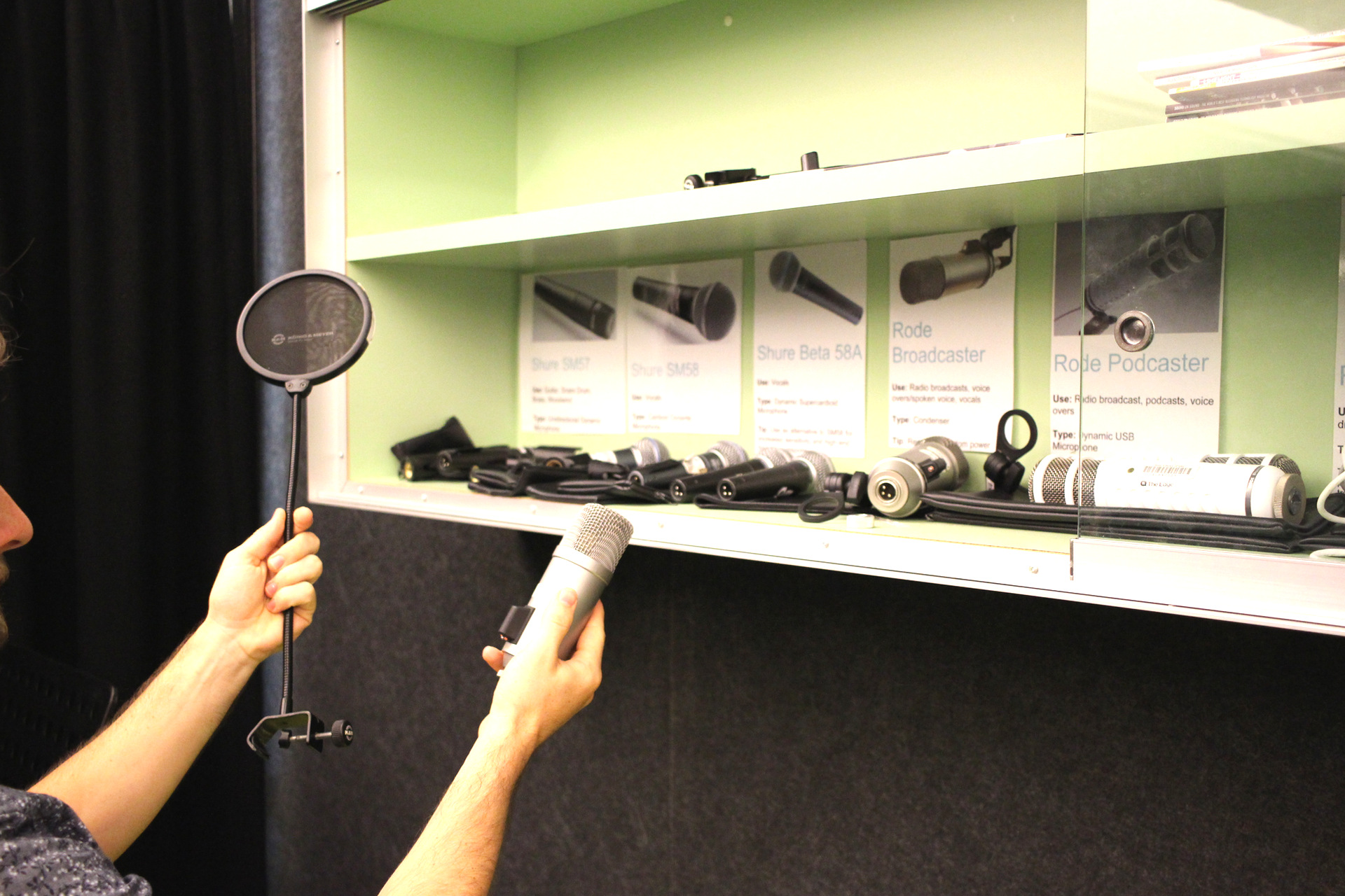
When you arrive for your booking, check in at reception and one of the friendly Visitor Service Assistants (VSA) will open the studio, and supply you with your requested microphones. You can view the available microphones here.

Safety
It is important to be aware of the safety considerations when using The Edge Recording Studio.
Duress Alarm
There is a duress alarm located on the left internal wall. This can be used if you need emergency medical assistance in the space. Please take note of the location of the duress alarm.
No Access Behind The Studio Equipment
Please do not access the areas behind the studio equipment. There are a lot of power and audio cables that can be a trip hazard. Additionally, if something is accidentally unplugged, you may cause damage to the equipment and make the studio unavailable for the next patron booking.
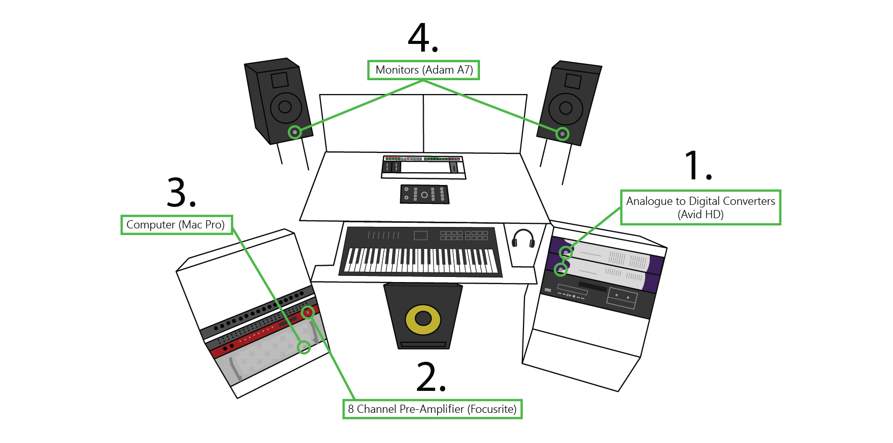
Studio Overview
Here you can see an overview of the recording studio hardware.

Power On
Begin your recording session by turning on all the required equipment. Power the equipment on in the order outlined below. Power off in the reverse order. NOTE: The studio equipment is turned on in this order to prevent damage and ensure all the hardware is communicating correctly
NOTE:
* The Denon CD / Tape player is optional. Power on after AVID converters if needed.
* The Korg Triton Keyboard is USB powered from the computer. If the Korg is not getting power, remove the USB cable at the top right side of the keyboard and plug it back in.
Monitor Controller
Check to see if the Audient Nero Monitor Controller (located in the centre of the desk) is set up correctly for your use case. The diagram below gives an overview of the mixer's controls as well as the inputs and outputs. The default layout for recording using a DAW (Digital Audio Workstation) such as ProTools, Ableton or Logic has been selected in the diagram below.

- HD 1-2: Monitor audio from all DAW's (ProTools, Ableton, Logic etc)
- Bluetooth Audio: Monitor audio from the Bluetooth audio receiver.
- Korg Audio: Monitor audio from the Korg Synth
- HD 3-4: Monitor audio from alternative headphone mix using output 3-4 from DAW.
- Volume: Volume control. NOTE: It is best to keep the volume down initially to reduce the risk of feedback when setting up mics.
- Dim: Qucikly reduces volume
- Cut: Mutes all audio
- Adam A7 Speakers: Ensure MAIN is selected from your OUTPUTS for playback through the studio monitors.
- Subwoofer: Monitor with the Subwoofer that is located under the desk.
- Headphones 1 -4: Each headphone output has its own volume controller and source selection. Select SRC (source) next to the headphone volume controller and then choose from the Input options. Headphone 1 is used as the main headphones in the studio. Headphone inputs 2,3,4 are available above the Audient Monitor Controller mounted into the desk.
Signal Flow
Audio signal flow refers to the path that an audio signal takes from the initial sound source to the final output. When using a microphone to record audio in The Edge recording studio, the audio signal flow is as follows:
- Sound source: This is the initial source of the audio, such as a voice or instrument.
- Microphone: The microphone captures the sound waves produced by the sound source and converts them into an electrical signal.
- Pre-amp: The pre-amp boosts the electrical signal from the microphone to a level that can be properly processed by other devices in the signal chain.
- A/D converter: The analogue-to-digital converter (A/D converter) converts the analog electrical signal from the preamp into a digital signal that can be processed by a computer or other digital device.
- Computer: The digital signal is then processed and recorded by a computer or other digital device, and can be further edited or mixed as needed.
Understanding the audio signal flow is important for setting up and troubleshooting audio systems, as well as for understanding the effects of different processing devices on the final sound output.

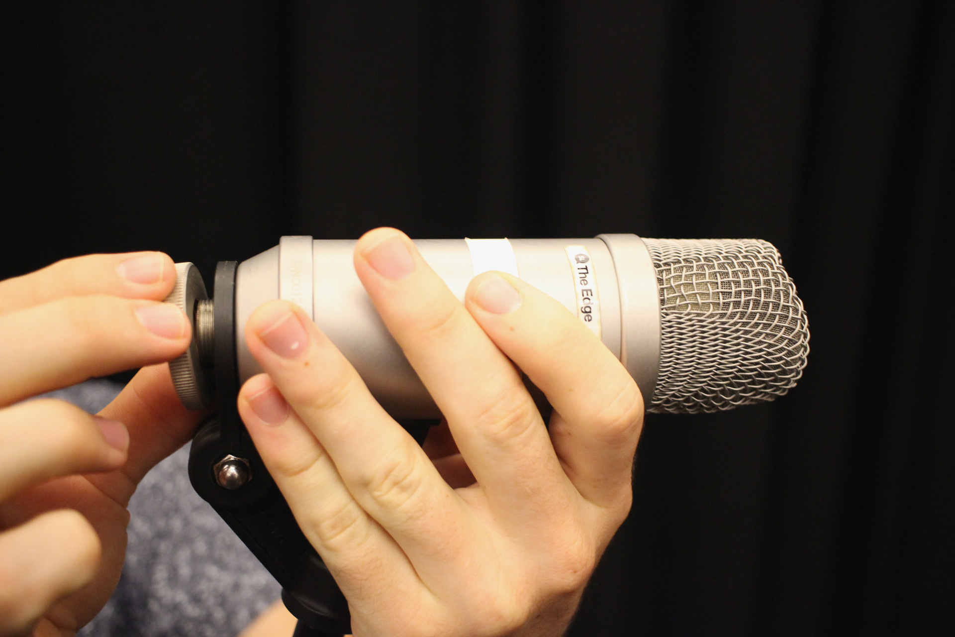
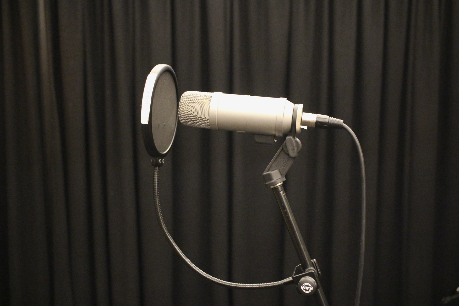
Microphone Set-up
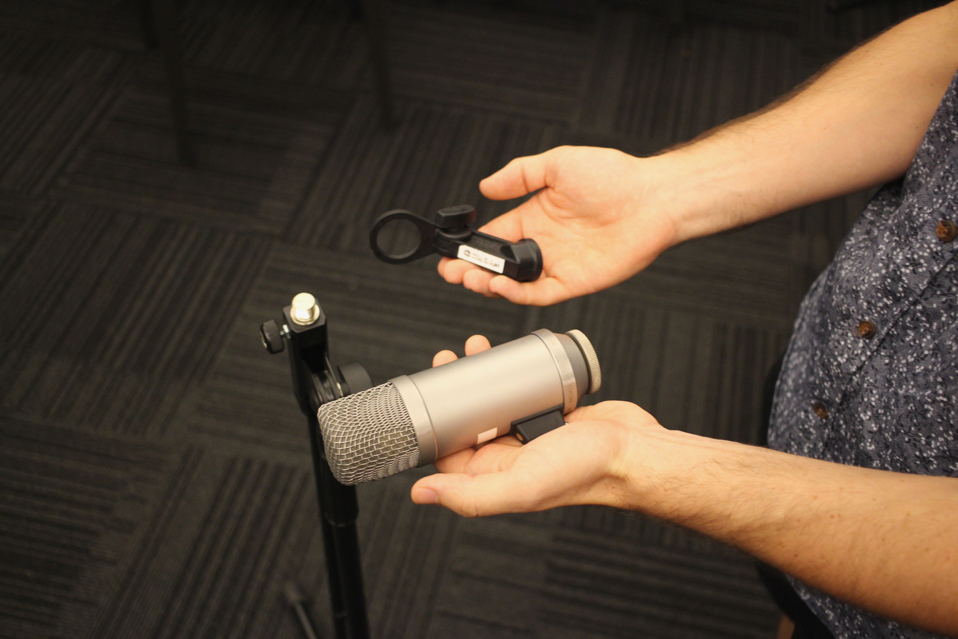
Grab your microphone and pop filter from the cabinet. We are using the Rode broadcaster.
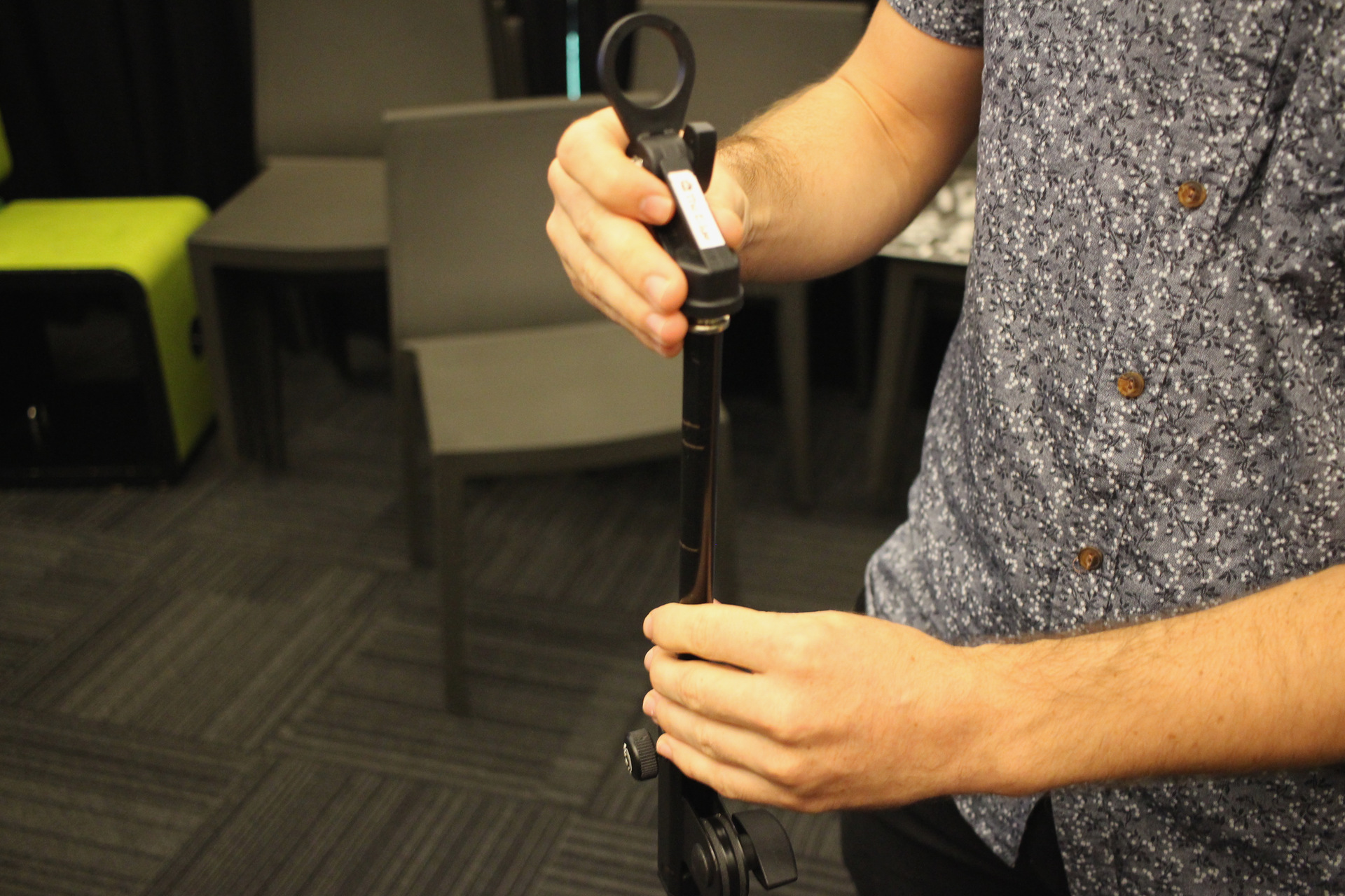
Make sure you have the right mic clip that attaches the mic to the stand.
Screw the mic clip onto the stand - twisting the mic stand shaft is easier.
Attach the mic to the clip, using the nut.
Grab a mic lead from the wall
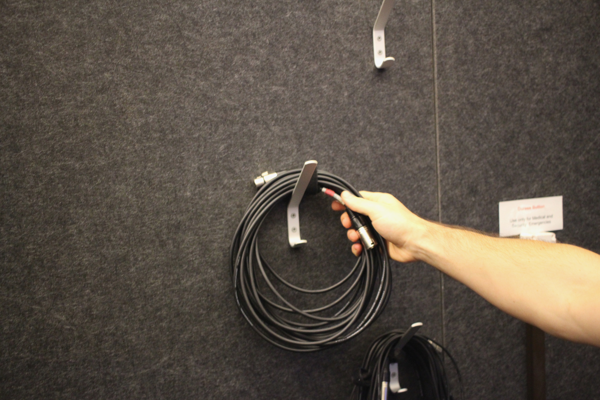
Plug in the female end to the mic.
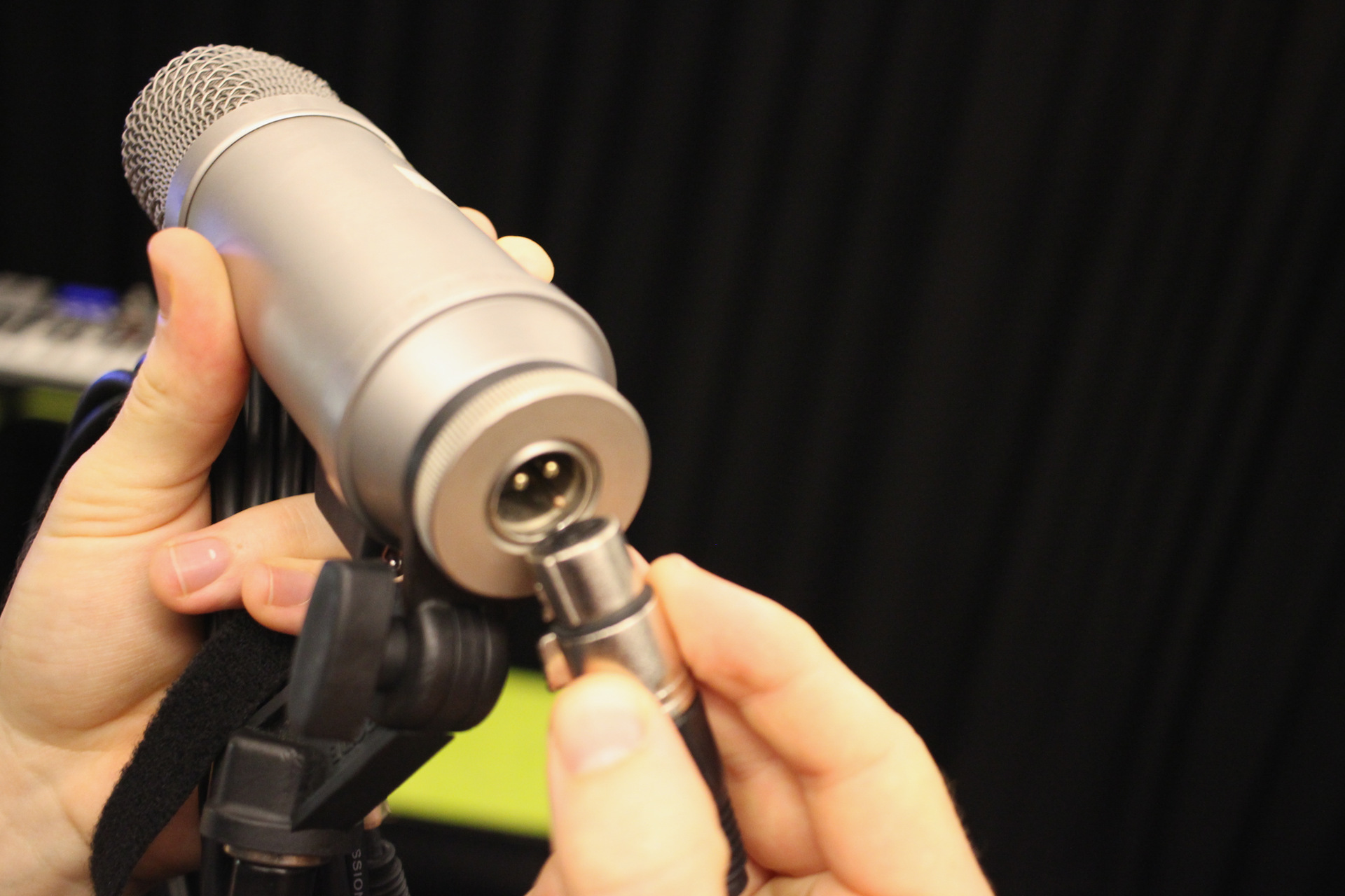
Tighten the mic stand
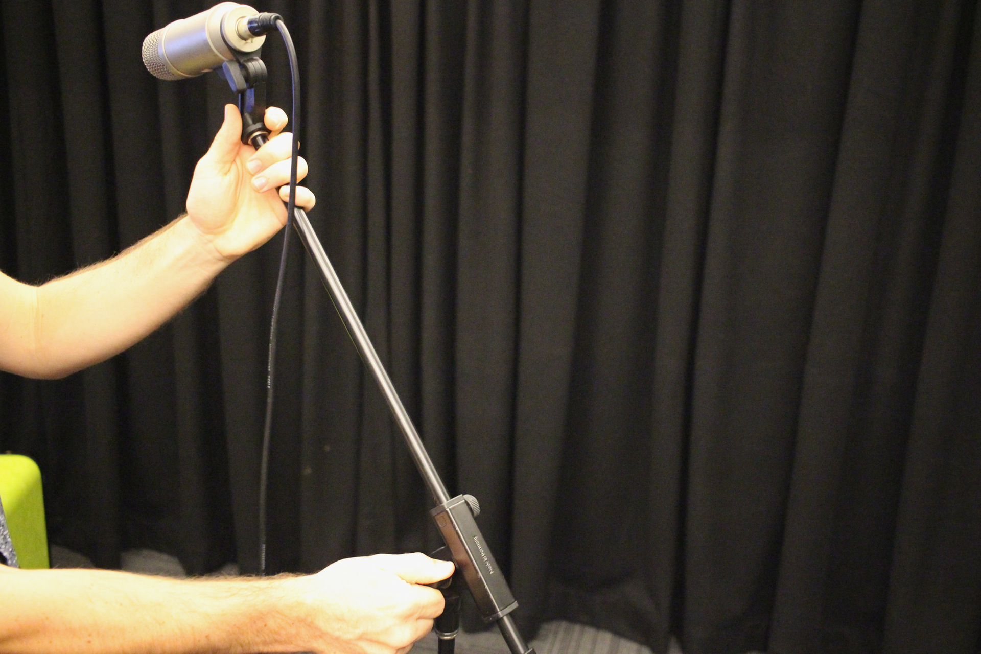
Attach the pop filter.
Microphone Pre-Amp Selection
Choose which mic pre-amp to plug your mic into. All the mic pre-amp inputs are accessible via the XLR Patch Bay and the Focusrite Pre-Amp. The diagram below labels all the mic inputs.
 Focusrite Pre-Amp
If you have chosen the Focurite, plug the male end of the mic lead into any of the inputs labelled FR 1 through to FR 8.
JLM Pre-Amp
If you have chosen the JLM's, plug the male end of the mic lead into the input labelled JLM 1 (JLM Dual 99v) or JLM 2 (JLM NV500).
Focusrite Sync Source and Sample Rate
When using the Focusrite pre-amp, you will need to ensure the SAMPLE RATE and SYNC SOURCE are correct in order for it to communicate successfully to the AVID HD converter.
Focusrite Sync Source
Ensure SYNC SOURCE is set to W/CLOCK (World Clock). When the SYNC LOCK light is green, this indicates the Focusrite is properly synced and the AVID HD converter is the Master World Clock.
Focusrite Sample Rate
Ensure the Focusrite SAMPLE RATE is matching the DAW's session SAMPLE RATE. You will need to manually select the SAMPLE RATE on the Focusrite. Press the SAMPLE RATE button to cycle through to the correct sample rate. i.e. If your Logic, ProTools or Ableton session is recording at 48k you will need to manually set the Focusrite sample rate to 48k

Pre-Amp Settings
Adjust the pre-amp to suit your use case. The below diagrams and descriptions outline all the pre-amp controls
 JLM Pre-Amp Controls
48v (Phantom Power)
If you are using a condenser mic, it will require 48v Phantom Power to be sent to the mic from the pre-amp in order for it to function.
Input Gain
Adjusting preamp gain is setting the right audio signal level to achieve clear sound without distortion. While the mic is directed at your sound source (Vocals, Instrument), adjust the Gain. Starting at 20, turn the gain control clockwise slowly until you have achieved the desired gain level.
Output Trim
The JLM pre-amps have a 2-stage gain structure. The second stage Output Trim allows you to fine-tune your gain by attenuating in smaller increments.
Impedance
Impedance in a preamp is the electronic resistance that affects the signal flow between components, influencing the overall tone.
High Pass Filter
80 Hz high-pass filter allows frequencies above 80 Hz to pass through while attenuating lower frequencies, effectively reducing bass and rumble in the audio signal.
20dB Pad
-20dB switch reducing the input signal level by 20 decibels, helping to prevent distortion and clipping when dealing with loud sources.
Phase
Reverse the polarity of an audio signal, which can help correct phase issues when recording multiple microphones or instruments.
Direct Input
Allows an instrument, such as an electric guitar or bass, to be plugged in directly and amplified without the need for a microphone.

Focusrite Pre-Amp Controls
48v (Phantom Power)
If you are using a condenser mic, it will require 48v Phantom Power to be sent to the mic from the pre-amp in order for it to function. NOTE: The Focusrite sends 48v in banks of two with separate buttons. 1-4 and 5-8.
Input Gain
Adjusting preamp gain is setting the right audio signal level to achieve clear sound without distortion. While the mic is directed at your sound source (Vocals, Instrument), adjust the Gain. Starting at 0, turn the gain control clockwise slowly until you have achieved the desired gain level.
Insert Master
Determines the function of the individual channel INSERT/AIR button. Inserts are used for the device's rear panel insert jacks for inserting external processing equipment,
Air EQ Master
Determines the function of the individual channel INSERT/AIR button. The “Air” circuit adds a boost to high frequencies.
Channel Insert/Air
Individual channel toggle switches that allow the user to enable or bypass the device's rear-panel “Insert” jacks for inserting external processing equipment, or add the “Air” circuit, which adds a boost to high frequencies.
Instrument Inputs 1-2
Inputs 1-2 on the Focusrite are combo inputs which means they can receive both XLR and 1/4 Jack cables. These two buttons set Inputs 1 or 2 to “Instrument” mode. When INST is selected, the gain range and input impedance are altered (relative to LINE), and the input is made unbalanced. This optimises it for the direct connection of instruments via a (TS) jack plug. When INST is off, the jack inputs are suitable for the connection of line-level signals. Line level signals may be connected either in balanced form via a (TRS) jack or unbalanced, via a (TS) jack
Creating Audio Tracks in a DAW
To create an audio track in your DAW.
ProTools
In the menu select, Track > New
Ableton
In the menu select, Create > Insert Audio Track
Logic
In the menu select, Track > New Tracks
Audio Track Overview
Below you can see a diagram of the audio track parameters for some of the most popular DAW'S suchs as ProTools, Logic and Ableton.

Choosing Audio Track Input
In your DAW, select the audio track input to correlate with the pre-amp your microphone is connected to.
Pre-amp - DAW Input
JLM 1 - Input 1
JLM 2 - Input 2
JLM 3 - Input 3
Focusrite 1 - FR 1
Focusrite 2 - FR 2
Focusrite 3 - FR 3
Focusrite 4 - FR 4
Focusrite 5 - FR 5
Focusrite 6 - FR 6
Focusrite 7 - FR 7
Focusrite 8 - FR 8
Setting Gain Level
You can use the dB meter in your DAW's audio tracks to help you set your gain level on your pre-amp. Setting the gain while the sound source is at its loudest ensures a clean recording with enough headroom to accommodate sudden spikes or peaks in the signal, preventing distortion and unwanted artifacts.

Playback Engine and Latency
Playback Engine
Playback engine refers to the hardware or software that is being used as the playback engine for your chosen DAW. In The Edge recording studio, the AVID HD analogue to digital converter is the hardware playback engine. Ensure HD Native is selected as your playback engine.
Latency
Latency can occur when recording through a digital audio workstation (DAW). There may be a slight delay between when the musician plays the note and when they hear it through the headphones. This delay is caused by the time it takes for the audio signal to be processed by the computer and then output through the headphones. This delay is the latency, and it can be an issue when recording or performing, especially when musicians need to hear themselves in real-time to stay in sync with other musicians or to maintain the correct timing and rhythm.
Changing the buffer size can help reduce latency when recording. A smaller buffer size means less delay but a higher chance of audio dropouts or glitches, while a larger buffer size means more delay but a lower chance of audio dropouts or glitches. Adjusting the buffer size can help find the best balance between low latency and stable audio playback.
In general, a buffer size of 128 or 256 samples is a good starting point for most recording situations, as this provides a good balance between low latency and stable audio playback without dropouts or glitches.
See the below image for how to change the PLAYBACK ENGINE and BUFFER SIZE in ProTools, Ableton, and Logic

Disks and Usage
All sessions must be saved to the drive named scratch disk.
File Privacy and Back-ups
Scratch disk is a temporary, shared storage.
- Scratch drive will be wiped and reformatted when full
- Other users can see and read/write/delete your files
Please take your files with you on an USB drive or stick.
Acorn Online Component
Acorn is our database that holds your induction access details. Please enrol into the specific induction you are completing with the SLQ Acorn website. NOTE: This website is only available onsite at SLQ. https://inductions.slq.qld.gov.au/user_login