FUN PALACE 2018 Steam punk LED
Cogs, a motor and a clever electronic circuit are put together to turn your finger power into light.
Activity Details
Type Ticketed (10 per session)
Duration 60 minutes
# Deliveries 4
Learning Outcomes
Participants will construct a manually powered gear-driven generator with a Joule thief circuit. This kit requires no tools, glue or soldering.
Session Plan
3 min - Show the participants a completed Steam punk LED device , and demonstrate how to use it. Discussion about how the device converts kinetic energy into electrical energy. 55 min - Guide the participants in constructing the device. Ensure each LED lights up after attaching the motor to the circuit board and before attaching the Joule thief to the middle plate. 2 min - Allow participants to use their device, troubleshooting if necessary.
Facilitator notes
This device is an energy converter that takes kinetic energy as an input, and produces electrical energy, and subsequently light.
Using a large gear to drive the small cog attached to the generator increases the rpm to a point where the output voltage is useful. The motor used can act as a generator because it contains permanent magnets set around coils of conductive wire which are attached to the shaft of the motor. When the shaft spins, these coils are moved through a magnetic field and a voltage is induced in the wire, available through the black and red tails on the motor/generator.
Turning this available energy into something useful is due to the Joule Thief circuit, and in particular the toroid. In simple terms, as energy moves through the wire wrapped around the ferrite toroid, a magnetic field is induced in the toroid, which rapidly collapses as the transistor reaches a threshold voltage and switches on. The collapsing magnetic field induces a spike of higher voltage energy in the secondary toroid wire, which is directed through the LED and causes it to glow if the threshold is reached. As this occurs, the transistor is turned off, and the entire cycle begins again. Because this happens very rapidly (about 200,000 times a second, depending on the specific characteristics of the resistor and transistor), our eyes see a continuous light rather than a flicker.
A useful analogy is to recall how clamping and then releasing a garden hose can cause a trickle of water to gush forth, though only for a moment. The Joule Thief achieves this effect repeatedly, and much faster by using well designed electronic circuitry. For a more detailed explanation (and examples of many variants and applications) - see References below, and find the 'Joule Thief' link in the sidebar.
Materials Req
Each participant should receive 3 packages
- 1 x STEAMpunk LED kit
- 1 x laser cut plywood base pack
- 1 x screw & nut pack
These packages will have the following materials
Body:
- 4 x M3 30mm Philips drive pan head machine screws
- 1 x M3 12mm Philips drive pan head machine screws
- 9 x M3 nuts
- 1 Mabuchi RF 300 EA low rpm DC motor, with 7-10mm bared and tinned tails
Laser cut from files: steampunk_led_body_cutfiles_v2.zip steampunk_led_extra_parts_v2.zip
- 1 each of top, middle and bottom plates (4mm ply)
- 1 set of 12 spacers (4mm ply) - included in top plate design
- 1 small wooden gear (6mm ply)
- 1 large acrylic gear (3mm acrylic)
- 1 M3 hex nut spanner (4mm ply) - included in middle plate design
- 2 motor supports (4mm ply) - included in top plate design
Joule Thief circuit:
- 1 red, green or yellow long leg, low power LED
- 1 NPN transistor (3904 or equivalent)
- 1 1K resistor
- 1 toroid (OD: 12mm, ID: 6mm)
- 17cm Figure 8 (paired) speaker wire (14/0.14 gauge), with 7-10mm bared ends
laser cut from: steampunk_led_circuit_v3.zip
- 1 printed Joule thief circuit diagram, on 0.6mm polypropylene backing
Equipment Req
This activity was designed to require no tools for participants.
for facilitator only:
- 1 x small needle nose pliers
- 1 x small side cutters
- Philips head screwdrivers
- wire strippers
- spare parts
- LED test rig
Instructions
Step One: Building the backbone
Begin by assembling the Top plate - the bits you will need look like this:

Take out the four long screws - these go in the corner holes as shown.
Make sure the plate looks like the image, with the top uppermost (you can tell the bottom of this plate because it has some etching on it) . The screws must go in from the top.


Thread a nut onto each screw as you insert it, and this will prevent things from falling out when you move the plate.
You can use the wooden spanner provided to tighten the nuts.


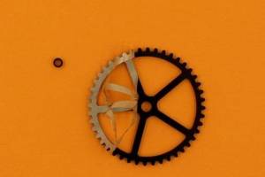
Step Two: Getting the first cog ready
When you have got the corner screws in place, stand the plate face-up again, and find the large acrylic cog.
This cog has a small spacer in the center, which you will need later, but you can push out the waste pieces from between the spokes.
If you twist them as shown, there is less chance of breaking the cog (but be careful).


Now you can push out the spacer, and peel the protective paper from all the bits.

Step Three: Attaching the first cog
Find the short screw, and slip the little spacer on to it. Then push the screw through the hole in the middle of the big cog.


Now insert the screw (with the cog attached) though the smallest hole on the top plate.
Thread a nut on from underneath, and tighten with your wooden spanner.
Give the cog a spin to make sure it is moving freely.


Step Four: Get the Middle plate ready
Locate the middle plate (it has the rectangular hole), and the packet of circuit parts. When you open the parts packet, these are the bits you need for now:


Take up the LED, and you should see that one leg is longer than the other.
LEDs only work when electricity flows through them in the right direction, and the different legs help you to insert the LED correctly (the long leg is the positive terminal).

The LED legs go through the two smallest holes on the middle board, and the long leg hole is marked with an “L”.
Push the LED legs through, then bend them apart a bit on the back to stop it falling out.


Step Five: Winding the toroid
The ring shaped object in your kit is actually a magnet, called a toroid. To make it work in this circuit, it needs to have two strands of wire wrapped around it.
Using paired wire makes it easy to avoid having overlapping wires, which would stop it from working.
First, cut a length of paired wire about 210mm long. It is easiest to strip both ends of the wires at this stage, but this can also be done later.
To start the winding, thread the toroid onto the wire, about 3cm from one end, and bend the wire around as shown below:


Now take the long end of the wire, while keeping hold of the toroid with your other hand, and loop the wire back through the centre of the toroid.
Then, pull the wire tight.


Continue threading the wire through, until there are 4 or 5 loops around the toroid. More loops actually reduces the effectiveness of this device, and it will still work with 4.


When you have finished the loops, you can trim the ends of the wire to about 3cm if necessary (scissors will work).


If it has not been done for you, separate the protruding wires (use a knife or cutters, or just pull them apart with your fingers).
Do this on both ends.


If the ends of the wires have not been stripped, do it now. Look closely and you will see one wire has a black stripe, while the other is all white (or grey).
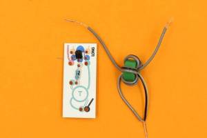
Take a plain wire from one side of the wound toroid, and a black striped wire from the OTHER side, and twist them together.
You end up with this:

Step Six: make the Joule thief circuit
The coloured circuit diagram has holes to take the parts of the circuit (you can push out any hanging chads with a pen).
Start with the transistor
The transistor is the small black thing with 3 legs. It goes in the blue holes.
Like the LED, the transistor only works when it is attached in the right orientation. If you pick it up, you will feel that it has a flat side, and a curved side (just like the blue diagram).
Insert the transistor so the curved side matches the blue picture (you might need to separate the legs a bit first).
In the picture below, this means the curved side is at the top, and the flat side faces the toroid.


Push the transistor down so it is close to the surface of the circuit board, and bend the legs apart at the back to hold it in place.
Then add a resistor
Now find the resistor - this only has two legs, and it works which ever way you put it in. Resistors can be brown or blue, and have stripes.
Bend the legs a bit, and insert them through the brown holes. Push it down onto the board, too.


When you look at the back of the circuit board, two wires are now adjacent: the middle one from the transistor and one from the resistor.
Twist these wires together as close to the board as possible. Then fold the twisted pair over and make sure they do not touch any other wires.

Now add the wound toroid
The printed circuit has a place for the toroid, outlined in green. take the plain single wire, and push the end through the hole at the end of the outlined green line.

Look on the back, and you will see this wire is beside the other leg of the resistor. Twist these two together.


The striped single wire from the toroid follows the solid green line, and pushes through next to a transistor leg.
Insert the striped wire, and twist these two together (bend them away so nothing is touching).


The joined toroid wires go through the hole at the bottom on the diagram, and can hang free until the next step.

Step Seven: Hooking up the motor
Locate the motor supplied, and the packet of small wooden bits. Open the packet, and find the small wooden cog.


Push the wooden cog firmly on to the motor shaft (it has to be a tight fit).


Take the black motor wire through the hole at the end of the black line on the circuit.
It comes through next to the joined toroid wires, and you can twist all these together.
(The cog is missing from the following images, but should already be on your motor)


Now take the red wire on the motor, and push it through the hole at the end of the red line on the circuit.
Twist it together with the other transistor leg that it is next to.


Step Eight: Attaching the Joule Thief to the Middle plate
The LED you put into the middle plate now needs to be hooked into the Joule Thief circuit (and this is a bit fiddly).
The two LED legs go through the orange holes on the circuit, with the long leg going through the hole marked “long”.
It helps to straighten the LED legs a bit first, and then you have to guide both legs through their respective holes at the same time.


As you can see, the motor fits into the round hole, and the toroid will fit into the rectangular hole when everything is in place.
The LED legs come through next to pairs of twisted wires on either side of the circuit, and each leg is twisted onto the adjacent pair.
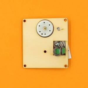
Make sure that none of the twisted wires are touching another lot of twisted wires, and test your circuit by giving the cog on the motor a sharp spin (anticlockwise).
The LED should flick on, but if it does not, try spinning the cog in the other direction (remember: the LED only works with current flowing in one direction).
A sharp spin can best be made by grasping the cog tightly between thumb and middle finger, and then snapping your fingers.
troubleshooting
If the LED still does not light up, check that there are no loose wires, and that nothing is touching where it shouldn't.
Most times, poorly twisted wires are the problem, but sometimes the transistor or LED may be inserted back to front.
It is not recommended to twist the wires with pliers since the wires may break (especially the transistor legs). Use great care if disassembly is required.
Do not go further if you can't get the LED to glow - it is hard to solve circuit problems once everything is assembled.
Step Nine: attaching the middle plate

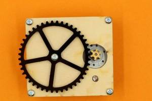
Turn the top plate upside down, and mount the middle plate onto the corner screws, making sure the small cog engages with the large cog.
There is a 5mm hole in the top plate to take the protruding LED.
In the packet of wooden bits, there should be 12 small tubular spacers (you might have to pop them out of their carrier first). Put three spacers onto each screw (even though only two per leg are shown).


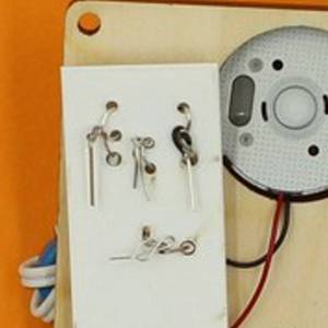
Step Ten: Attach the bottom plate
Find the bottom plate, and also the two circular wooden motor supports from the pack of wooden bits.
Place the motor supports so the holes in these pieces sit over the bump on the bottom of the motor.


Without dislodging the motor supports, guide the bottom plate onto the corner screws.


You may need to press down firmly on the bottom plate to attach nuts to the corner screws (pressure also helps keep the motor support in place).
Use the wooden spanner to tighten the nuts.
Assembly is finished, and spinning the large cog in the correct direction (clockwise) with your finger should make the LED glow.


Files
steampunk_led_facilitator_presentation.zip
https://wiki.edgeqld.org.au/doku.php?id=workshops:public:steampunk_led