Hack the Evening Retrofuture sideshow alley Project
Blog post about the Project on the State Library Project
Pile of Resources on the State Library Website about the Ekka
List of projects
Heres a list of the different projects different people are working on. To get your project added talk to us at HtE or email appliedcreativity@slq.qld.gov.au
| Title | People working on it | Description | Inspiration |
|---|---|---|---|
| “Wind Jammer” Chair ride | Dianne | Traditional swinging chair ride | |
| Carousel | Michelle | Traditional Carousel | |
| Shannons Hot Chips SpaceBus | Mick | Byrne Family Favourite Shannon's Chip was established in Crows Nest in 1948. | 2016 CM story on Shannon's]Chips  Shonnon's FB Shonnon's FB |
| Shipping container filler | Luke | ||
| Gravitron | Luke (taken over by Carolina |
Adding LEDS
hey just wanted to share the work i did the other day coming up with a led solution for the miniatures. We have a pile of 12 AC - DC adaptors bought out of flood money last year https://www.meanwellusa.com/upload/pdf/GST18B/GST18B-spec.pdf. I think there is about 20 of them. In alot of cases this will be better than using batteries. Batteries cost money and need to be replaced.
but how do you get an idea for a circuit diagram and what resistors do you need in the circuit so the LEDs don't burn out?
The answer is here. LED calculator . net lets look at an example of what Carolina has been working on and who I went about supporting her to prototype a solution.
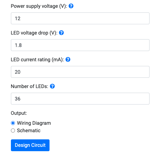
Carolina wants to mount a total of 36 leds into her gravitron (4 leds on each of 9 panels)
That’s 36x standard colour LEDs powered by one of the 12 V power supply above.
Step 1 - Look up the info we need for the calculator
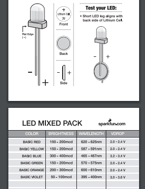
look up the data sheet for the LEDs. Heres the one for the Coloured LEDS we currently have in stock data sheet & SparkFun LED Tutorial and find the LED info for the LED calculator . The info sheet didn’t have much detail
but the tutorial had this handy table.
So between these two we have the info we need
Step 2 - Enter this info into the calculator
Step 3 - Gather the components
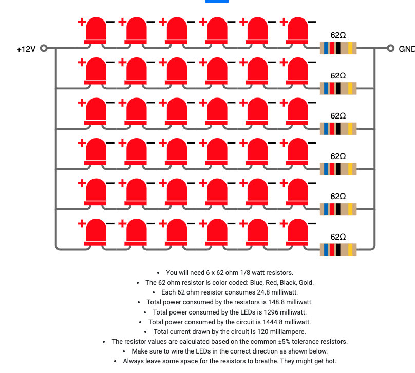
We grabbed the 36 LEDs • 6x 47Ohm resitors (close enough, our packs didn’t come with 62 Ohm resistors) • 7 x breadboards • Jumperwires • 1x 12v power supply
Step 4 - Check we understand how a breadboard works
use the multimeter on the Continuity setting to demo how the bread boards work
Select the continuety setting by
• selecting Ohm on the Dial ![]() • And use the blue button in the image above to select the continuity setting
• And use the blue button in the image above to select the continuity setting ![]()
On this setting the multimeter beeps when there is continuity between (electrical connection ) between the 2 probes
Step 5
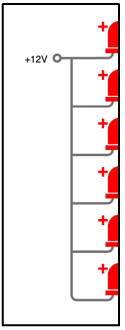
Then we populate all these components in the circuit onto a breadboard using the Circuit Diagram the calculator produces.
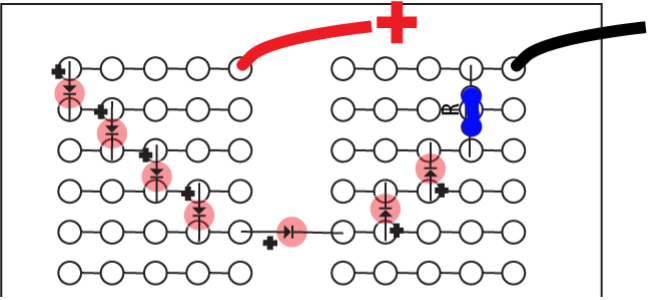
We made 6x of these
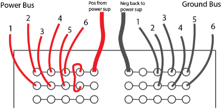
On the 7th Breadboad we made a
common 12v+/ (positive (+) terminal.
And a common Ground /(-) terminal
Step 6
Apply power to it from the 12v Power Supply. Chances are you’ve made mistakes (especially with the polatirty of the LEDs ) but there’s a good chance that you have at least some of the LED gangs right and these should work. No set about fixing the parts of the circuit you didn’t get right.
Check for the following
• Dead LEDs Test the LEDs that don’t work on a calculator battery you know is working • Polarity is wrong on LEDs
Once you have this all sorted ( as a prototype on breadboards) you can work out how your are going to run your wires in your actual miniature.
