Giant Cardboard Structures
This part of the Grumpus project will involve volunteers and design students working in collaboration with AC staff.
By some process a single idea will be drawn from the Well that has been filled with the products of children's imagination.
Design students will then work to develop a prototype concept that can be constructed at large scale (~5m), using either digital or physical manufacturing techniques. Students and volunteers, working with AC staff will then build the object using cardboard (or other cellulose based materials) for installation at different sites during the Grumpus program. The constructs will be modular, and so able to be dissassembled and re-assembled at different locations as the need arises.
During design and construction, other elements may be added (sound, lighting, motion) using electronic or other technologies. Decorative treatments will use a strict colour palette determined through the visual identity process.
At the end of the project, electronic and mechanical components will be recovered for re-use, and the cardboard will be recycled.
This documentation by Peter Musk, 2021
Making Giant Things from Cardboard
Cardboard is ubiquitous, cheap (or free) and recyclable. Most people have had experience working with it, and there are widely available and well resourced methods for cutting and joining it. These are some of the reasons that State Library chose cardboard as the medium for our first foray into making giant things, as the Great and Grand Rumpus filled an entire floor with the materialized products of young children’s imagination in 2016.
We would like to invite you and your communities to explore this creative space, too, as part of the Greater and Grander Rumpus (or Grumpus, between friends) in 2121. And since libraries are fundamentally public spaces for information sharing, we would like to share what we learned about working with cardboard at grand scale.
All Ideas are not Equal: Turning Concepts into Cardboard
Assuming you have chosen a few ideas from the apparently bottomless well of children’s imagination, what might you think about before firing up the glue guns?
Gravity is a thing.
Making something that does not rest securely on the floor will be harder. Big things made from cardboard can still weigh a lot, and an object that is cantilevered or top heavy will need an engineered solution to avoid collapse and the crushing of spectators. Counter weights, internal supports or even suspension can be a solution (this is how we made the 3m moon hanging in our auditorium), but you will need to get advice from safety professionals, and maybe engineers.
Doors and floors.
Not many buildings are made with Giant Things in mind – and if you are going to make something somewhere other than where it will be displayed, then getting it through the door or up the stairs can be an issue (speaking from experience, here). In the absence of accommodating facilities managers, you can make it in segments, or build it on site. A public build is also a great way to generate interest (and maybe attract volunteers), but can get untidy.
Right brain vs left brain.
This choice is founded in the skills of your crew, and your volunteers. Fundamentally, it is whether you take a fabrication approach (scale drawings and digital models) or a sculptural approach (adding detail to a stable skeleton and building in the moment). Some things lend themselves to one approach (a giant snot monster is not going to need orthographic drawings, for example), but either way can work. More on this, later.
Passive or participative?
Experience beats observation every time. Making your giant things available for visitors to climb through, pull on or open and close will create a deeper engagement, more interest and headaches for the OHS officer. Things need to be made very robust to survive contact with the audience, and you will need to allow for repairs. This is also where sensors, servos, flashing LEDs and Arduino controllers can come into play – if you have experienced talent on hand. Including technologies means designing for wires, holes and power supply from the outset.
The vibe
Cardboard can be ugly and monotone. While there are some surface treatments that can be used (more on this later), it is the skin of your thing that people will respond to first – and especially the face, if it has one. This is where art workers are gold – sculptural techniques and a sense of line can bring a hulk of dull cardboard to life. Painting and decorating is a curatorial decision - and a lot of work (since that material needs to be sealed to take paint well). Sticking to a defined and limited palette helps. You can also use digital tricks (like projection mapping or AR) which have the added benefit of being interactive.
Still reading? If all that has not frightened the idea out of your mind, then more practical tips and hard earned learnings follow.
Design
Translating an idea from the Well into a viable plan for construction needs to involve considering the intrinsic nature of the material, basic engineering principles (gravity, again) and authentic artistic interpretation – which is why getting some experienced industrial designers on board is a very good thing. A professional looking design concept still has to survive the realities of fabrication, though, and so always be prepared for some fine-tuning along the way. This might mean the sacrifice of delightful, but impractical ideas to the implacable gods of time, money and cardboard. Our experience is that the magic of grand scale and childlike whimsy will still be actively in your favour, and the visitors will not ever know what they are missing. Simple is good.
An agreed concept drawing is an essential starting point, and adding a scale is also vital. Artistic renderings can suffice, especially if they include views from different angles. Having these drawings in physical form for fabricators to have at hand for quick reference is also a useful thing. If they are hand drawn, make sure there are copies made. Annotation of changes should be part of the fabricators job, and helps make for a more robust and reliable process – having the sole keeper of knowledge absent for whatever reason can needlessly complicate the build.
Your solution to designing will depend on local circumstances, and there is no best method. Sculptural approaches can be quicker, if talent is available, but the result will tend to be more an interpretation than a faithful reproduction. Digital methods are reproducible, transmissible and can activate advanced manufacturing technologies if these are available.
Sculptural techniques.
Talented 3D artists can apparently pull things from the air, but if you are less gifted, or a beginner, then a few tricks seem to be commonly involved:
- Reduce to some simple geometric primitives to start. An elephant can become a few various ovoids on top of some cylinders, for example. These basic shapes can then be reduced to a skeleton with joints and ribs to carry the skin.
- Build a skeleton to bear the load and carry the profiles. Arches are good, or angles with gussets for strength. Adding a profile piece around two or more rigid bones will keep it in place, and spread the load. Triangular section beams are less prone to collapse than rectangles or squares.
- Work the cardboard into shape mercilessly. Creases, folds, twists and rolls can all add suggestive detail to your shape. Lightly spraying the cardboard with water will relax the material, and make bending into curves easier (but might repel the glue).
- Add lots and lots of bits. Build up the shape with many small additions, rather than trying to make it all happen in one piece, a bit like sculpting in clay. This is especially so when you come to the final skin – lots of detail (scales on a fish, for example) is visually entrancing, but also lots of work. If you can use repeated elements that can be produced easily (with a CNC for example, or physical jigs) time can be saved.
Digital techniques.
Commercial 3D modelling software is widely available for engineers and artists with the budget. Free open-source varieties are available, too: Tinkercad builds from simple primitives, but is easy to learn and surprisingly versatile (if you have the time); Blender is complex, detailed and poweful (if you have the time). Both have legions of enthusiasts on Youtube happy to guide you for free. Slicing a 3D model can produce ready made profiles, but you will still need a skeleton to hold them in place. Again, some tricks are ubiquitous:
- File security and version control are fundamental. Having all the design files on one laptop that can break or be left at home is courting disaster, and informative file names are a help, too. The cloud can be a wonderful thing.
- Not all files are the same. Commercial software especially seek to deter competitors by using proprietary file types that may not travel well between software packages. Use a 3D file type (not an image like jpg or png) that works across platforms - .obj is our choice.
- Slicing the model can be done using a free download from Autodesk (Slicer for Fusion 360 – see details later), or more laboriously using Meshmixer (another free download). Slicing in two dimensions (X and Y most commonly) will produce 2D shapes that can interlock to give a 3D shape. You still need to build something to hold everything in place, though, and using a registration system to align the parts in space is vital.
- A foldable net can be made from the surface of your 3D model (details later), but this can produce a fiendishly complicated puzzle of pieces, and is almost never done. It could work for simple shapes, with a few flat surfaces, or a low poly model made with this in mind.
- Digital design can be very time consuming, especially for the keen novice. It is easy to be consumed by details that will not be significant in the final build.
Physical Construction
A note about nomenclature
As this document has developed, a way to refer to different (but recurring) parts has developed. Open to discussion, but this is what follows:
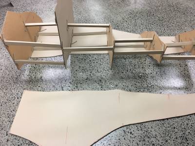
element refers to the slices (or layers) made from the 3D model that have been drawn to scale on the CNC, and cut from cardboard. Thus, the verticals in the construct that follows are labelled Y-elements . Horizontal bits (that may be used to transfer lateral shape to the model later) will be Z-elements.
module is used to refer to each of the sections that have been arbitrarily imposed to make the construct relocatable. Simple labels (like Left Hand Side (LHS) bottom) describe how they fit together - remembering that LHS is as viewed from the front.
plate or 'join plate' has been used to label the flat sheets that separate the modules. For example, the lower LHS module will have a plate on top that joins to an identical plate on the bottom of the upper LHS module. These plates are what the wedges press on to hold everything together, and give rigidity to the modules when they are disassembled. The upper LHS module will have a central join plate as well (but not the lower LHS, since this part of the construction is hollow).
rib refers to the triangular constructs used to join the elements. Ribs are supposed to be aligned with the X- and Z- axes of the model (that is, square to the Y-elements, and parallel with the floor)
Ribs
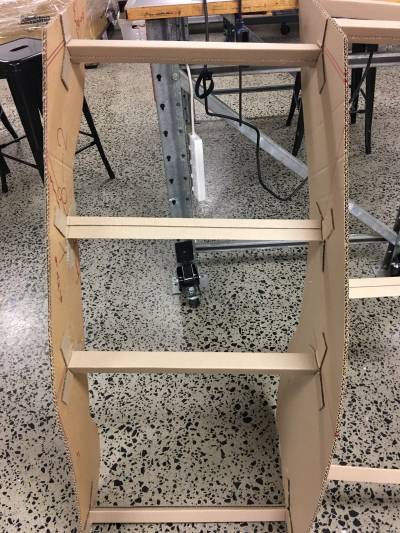
A system of ribs was devised to separate vertical Y-elements. Key attributes:
- standard length (46cm) between attachment points. This dimension was derived from the spacing between slots in the 3D models. Using this dimension allows for efficient use of material - two ribs can be cut from each length of pallet pad cardboard. Pallet pads are approx 1150mm square, so half (575mm) gives 115mm excess (or 57mm at each end) for attachment.
- triangular section for strength
- each face of the triangular rib 35mm (the width of a standard 1m metal ruler), with half that as overlap for gluing closed.
- double length ribs used (with the flat side up) as supports for suspended Y-elements
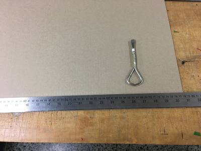 Rib layout, with scoring tool (use the ROUNDED corners so the cardboard is not cut)
 Scoring completed - note that cardboard is NOT broken along the score. This maintains strength.
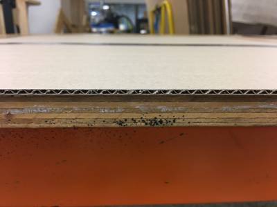 Grain (corrugations) runs across the long edges of the rib for strength.
 Cut the rib down the middle of the fourth parallel - this gives a gluing tab to both adjacent ribs.
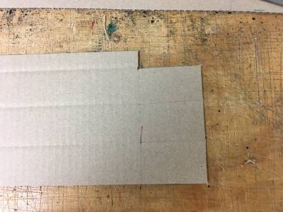 Remove corners of the tab as shown to make it easier to open up and bend back the attachment tabs.
Gluing the Ribs
After trial and error, the following seems the easiest method for closing the ribs while ensuring a securely glued product:
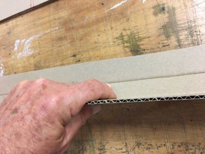 Start by folding the creased rib along the first complete score line
 Continue to the next fold, rolling the triangle towards the glue point. Keep downward pressure on the vertex with your hands.
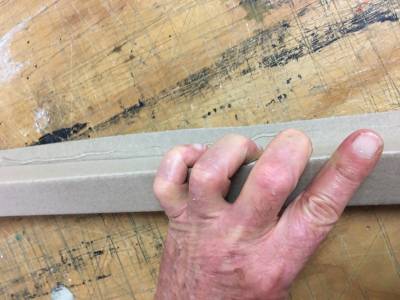 Run a bead of glue along the glue tab (both ends and a bit in the middle is usually enough).
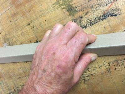 Roll the rib onto the glue, and hold down ward pressure until the glue sets.
This method gives a firm fix along the length of the rib, assisted by downward pressure along the length of the rib. It is easier to keep alignment along the folds by pressing towards the centre simultaneously. (press down and towards yourself).
Attaching the ribs
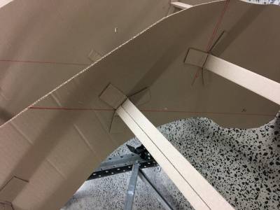
The ends of the ribs were opened up by cutting down the vertices to the 46cm mark. Each face was then opened up, and glued flush to the Y-element.
Aligning ribs to keep them horizontal and parallel to the centre axis of the model was an issue (another reason for lots of registration marks).
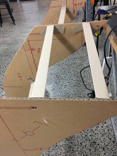 Ribs glued with a flat face flush to the top edge kept this face horizontal, and gave a surface for gluing on a top plate. (Note that one of the rib glue tabs has been removed, rather than bending it over the edge, and so introducing bumps).
Adding angle supports
A join plate was attached to the module upside down - by laying the plate on a flat surface, and gluing the module onto it, using Y-registration marks added earlier. Because the module was intrinsically imbalanced, extra supports were devised to help keep the Y-elements attached to the plate.
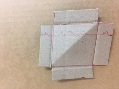
A few rough quadrilaterals were made from waste, then scored and folded along a diagonal axis. These were folded to make rightangle, and glued in place to anchor the end Y-elements
A better (but more labour intensive) design for angle supports
The angle supports used above worked to a point strengthening the join between vertical and horizontal parts, but did not provide much resistance to the vertical elements moving out of plumb. They kept the pieces together, but did not keep them square. Another design was used later, with an extra fold to provide better bracing:
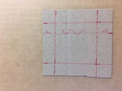
Cut a square from scrap material, with a 10-15mm margin marked all round.
The size of this square will be set by the location of the support - it has to fit between ribs, and away from wedge holes.
The corners are cut out to allow folding
Flip the piece over, and make a diagonal score along the back. On the front, score along the margin lines
Pinch the corners together down the diagonal fold. Fold the margins upwards.
Glue together the centre of the triangle, and press firmly until the glue hardens. Fold the margins out of the way while the glue sets .
Attach the supports by adding glue to the underside of the margin flaps, and pressing it firmly into the angle between the two sheets you are joining. You can see why these supports were made small - there is not a lot of space between ribs in places.
Digital Techniques
In some cases, a digital approach to designing your Giant Thing might be preferred - if you wanted to hack an existing form, for example (such as making human sized Lego figures, or re-imagine some real world building with fantastical elements). This approach requires a good grasp of 2D and 3D design software, access to technologies that can use these inputs, and a lot of time. If this is something you want to explore, as a way to increase your skills, then expect to need even more time.
As with all things digital, there are many ways to achieve the same end, each with their positive and negative aspects.
Design Software
There are lots of competing software packages for both 2D and 3D design, and while some are commercial (and can be very expensive) there is usually a free, open-source software option (FOSS) available. More importantly, some are better suited to producing technical working drawings than others - graphic design software like Adobe Illustrator is optimised to produce assets for graphic display (on screen or in print), and while it may be possible to produce files in a format that can be used to produce physical objects, they may emphasise appearance over accuracy. Similarly, 3D design using Blender can produce detailed models, but techniques that result in very complex meshes with high polygon counts might not be suitable for manufacturing other than by 3D printing at small scale.
In most cases, you will be using a combination of different packages, and moving between 2D and 3D environments to generate useful patterns for your Giant Thing.
2D Design
Adobe Illustrator is costly for intermittent use, but can produce the svg files needed to make templates and drawings. It also has useful tools for transforming simple artwork into editable, digital forms by tracing (but this can involve lots of time refining the input).
Corel Draw is a CAD focussed 2D design software, and has many more tools that make drawing accurate and scaled designs easier. Like all commercial software, it tends to rely on closed file formats (that might not be accessible by other software packages), but there are still ways to produce svg or dxf files as needed.
Inkscape is a powerful FOSS 2D design package which will do almost all you require. It does seem to have some instability with maintaining accurate dimensions, and this needs to be monitored. This is the software of choice for an impoverished hobbyist.
Image Manipulation Software
Photoshop, GIMP and Paint are all geared to produce digital images (jpeg and png formats), and will not provide the sort of files you will need to make something (other than a picture).
3D design
Tinkercad is free, but limited. A good place to start getting used to working in a 3D environment, but hard to produce detailed models without lots of work. The interface also makes accuracy difficult to maintain, and even the geometric primitives used are not ideal for fabrication - circles may not be circles! On the other hand, access to the enormous free database of existing models is a benefit.
Fusion 360 like Solidworks are industrial grade 3D modelling programs , with a strong bias towards engineering products. Hobbyists can get a free temporary license, but the learning curve is very steep. Modelling using the sculpture tools tends to produce complex meshes, which might be a problem for manufacturing technologies.
Blender is a FOSS 3D modelling package which allows for fine editing of a mesh, and outputs files in a variety of useful formats. This is the one I use for complex meshes.
Meshmixer is free for download from Autodesk, but is no longer being upgraded or supported (since most of its functionality has been incorporated into Fusion 360). This has some tools for manipulating a mesh, but does not allow editing of individual vertices (as the points in 3D space are called).
Going from 3D to 2D and back again
Unless you have a 3D printer that is as big as a house (and which is tooled for paper pulp) a 3D mesh will not be useful for manufacturing your Giant Thing. Luckily, there are ways to derive 2D templates and guides from the 3D model, using slicing software developed for 3D printing. If your Giant Thing is some elaboration of a box (such as a house, for example), then you might be able to make 2D files from each aspect, and join these together to make the object. Once you have curves involved, then slicing is your only recourse.
Here is a work flow that has been successful for us:
Begin with a 3D model
You can create something from scratch (using Fusion 360, or Blender, for example), saved in a transferrable format (such as obj or stl), or begin with something available without copyright. Thingiverse has many models (mainly created in Tinkercad, with the caveats mentioned above), and there are many other websites offering models for free, or at low cost. Museums have also begun 3D scanning items from various collections, and archaeological or biological specimens are becoming available (the Smithsonian posts their s at https://3d.si.edu/ , for example).
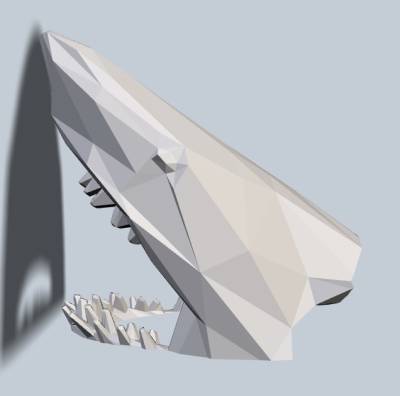
We made this shark in Fusion 360:
Import your model into Slicer for Fusion 360
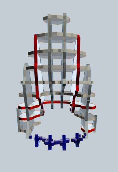
This very useful software gives options for slicing to make larger models, and gives you control over the number and direction of slices. Other slicing software (for 3D printing) may allow you to export slices as svg files, but you will get far too many of them, and they may not be well ordered. In the Construction Technique panel, choose the option for interlocked slices, and you get this:
Export your slices in a 2D format
When you select the 'Get Plans' button, you can download the slices in a pdf format (other formats are available, but pdf's are the most widely useful). You may need to adjust the size of your material (in the 'Manufacturing Settings' drop down tab) for slices that are too big. Alternatively, scale your model to fit the page, and then scale it back up again before using. The plans look like this:
Import the pdf into a 2D design program
We used Inkscape, and the file opens like this:
Note that there are no registration marks on this design - something vital for you to add before manufacturing.
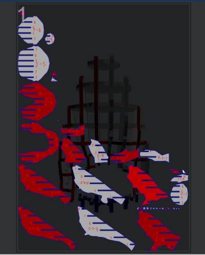
Registration marks are inserted by the slicing software, but only if you choose 'Stacked Slices'. Unfortunately, this method gives far too many slices for a truly large build (the resulting model will be solid, and made of many layers), and you will have to decide which you want to use. On the other hand, if you do this, the plans pdf you download will have registration marks corresponding to the placement of dowels. You can see them here:
Conclusion
As you can see, there is no simple and easy way to do this - getting a clean, registered set of 2D files for use with a CNC or plotting machine will always involve moving between several software packages, and a bit of editing of the resulting 2D files. All of which takes time.
This is a very brief walk-through, and there are lots of details you might need to now. Luckily, Youtube has countless 'how to' videos of varying quality that will explaining the methodologies for each of these software packages. And there are always the manuals, only a Google away.
