~~REVEAL~~
Parametric Phone Case
Rationale
This workshop is a try-it to introduce our users to Fusion360. With the educational and startup licenses available for fusion360 and the need for internal CAD design software it seemed like a good time to run a try-it. The workshop also serves to introduce the constraints of the laser cutter and materials.
Activity Summary
Introduction to Fusion 360 CAD Program, making a basic model of your phone, then a phone case.
This is the first of two workshops. The second workshop covers practical design and construction of the case using the laser cutter.
Materials
Phone
Tools
- Fusion 360
- Laptops
- measuring tools (Tape Measure, ruler, or vernier calliper)
Instructions
Step Zero: Before we Start
Turn on your Fabrication Lab laptop, log in as 'edgeuser' with the password 'edgeuser' and open Fusion 360. New Fusion360 users will need to create an account.
Step One: Getting Started
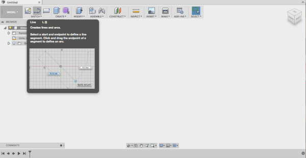
- Open Fusion 360. Lets look at our map of Fusion 360.
- Click File and save. Name as 'myphone'
Step Two - Make an Assembly
In the tool bar click Assemble then Make a component.
- An assembly is an organisation of parts (components).
- Multiple assemblies can be joined together to make a whole product.
Step Four - Making a Sketch
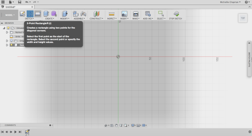
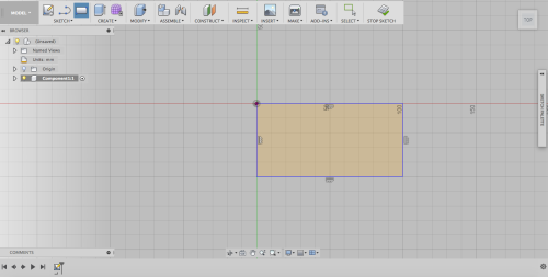
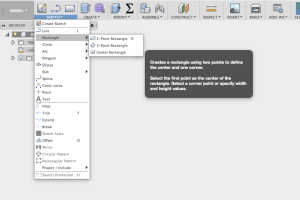
Select the rectangle tool
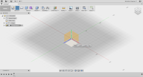
then choose a plane to draw on,
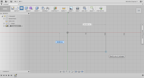
and draw a rectangle.
Once the rectangle is complete, it is filled in with a solid colour to indicate it is 'sealed'
Playing With Parameters
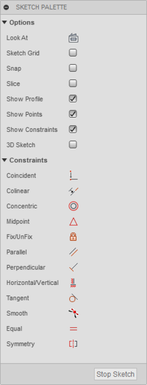
Constraints are geometric properties that can be used to control your sketch. For a comprehensive explanation check out the wikipedia page.
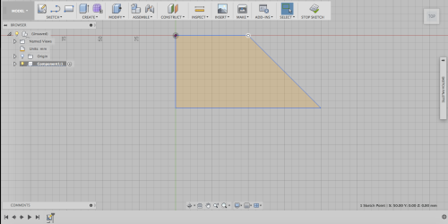
Then change some parameters, and try to move your shape.
Then click stop sketch when you are done.
Now that you have done some exploring in Fusion, go to file and open a new design for a fresh start.
Step Seven: Measure Your Phone
Pull out your phone, and measure its length, width and depth (not including the camera) using the vernier calipers
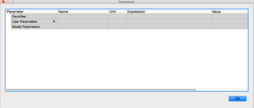
In your new design click parameters in the tool bar (it can sometimes be under Modify). When the window appears click the little green plus to enter new information.
Then making sure the measurements are set to mm enter the length, width and depth of your phone into the table one by one. At the end select all the stars to make them all favourites.
Sketching your Phone
Begin drawing the rectangle from the origin. Before clicking to creating the rectangle two measurement boxes appear.
In the width box write width and click enter.
Then click tab which will take you to the length box.
In this box type length then click enter and then enter again.
Check that the rectangle cannot move then once done click stop sketch.
Extrusion
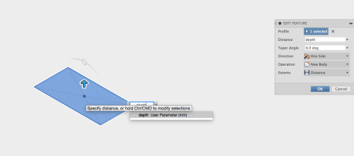
Click the rectangle the click create then extrude. A window will come up to the right. In the box next to distance type phone depth(or whatever you named your phone depth in parameters). A selection box asking if you want to assign the parameter phone depth will appear. Click on it then click ok.
If your phone has a curve, using the vernier calliper measure the distance from the table to the thinnest piece of phone If your phone doesn’t have a curve skip this step).
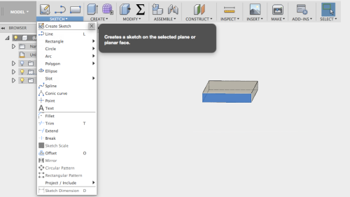
Using these measurements click on the end face and click create a sketch.
Now click arc/3 point arc.
Using the 3 point arc click the start point on the left edge
and the end point on the right edge
then click the bottom.
Then click stop sketch.
Cutting an Arc
Now using the extrude tool
click the bottom section that you just created on the edge face,
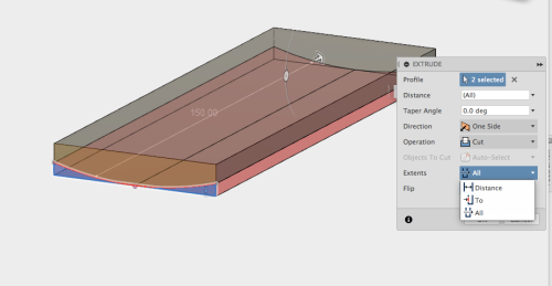
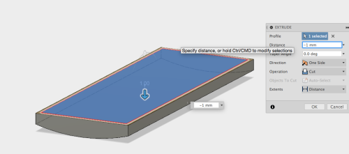
then change the setting from new body to cut.
Using the arrow on the screen change the extents. Once this is done change the extent from “distance” to “all” . Then click ok.
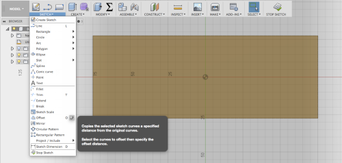
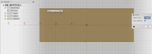
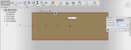
Now click the top face and click sketch. Then click sketch then offset. Click the outer line on the phone. In the offset distance put 2mm. Then click ok and stop sketch.
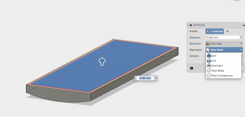
Now click the inside rectangle and click extrude. In extrude change new body to cut then put the measurement in as -0.1mm (this will change the direction of the cut). Now click ok. You have just created a phone screen.
Using the design history, click the sketch for the offset you just created. Then once in delete the offset constraint. You can now move the bottom line up to allow room for a button. click exit Sketch
Click sketch, center point circle, then the top outer surface and then draw the circle in the center at the bottom. Once you are done click exit sketch.
Click Extrude and click the circle, then extrude by 0.30mm.
Filleting
Click Modify, and when the menu drops down click Fillet.
Now Click all four edges of your phone and enter into “radius” 5mm. Then click ok.
Rendering your Model
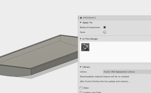
Now using the keyboard click A, then the appearance window will appear. Make sure the bodies and component option is selected (this will allow you to cover whole components with an appearance).
Select an appearance and drag it onto your phone.
Now select the face selection (this will allow you to apply an appearance to faces only).
Select an appearance and drag it to your phone screen.
Click Model and a drop down menu will appear. Select Render. You have now created and rendered a basic phone.
Lexicon: Body: the physically formed part of a model. A body is within a component Components: A component is a part in the working model. Assembly: The formation of many components to make a complete model. Extrude: To pull a 2D sketch into a 3D form creating a body. Sketch: A 2D drawing that can later be extruded 3 Dimensionally Plane: A invisible surface to sketch on which can exist on the bottom, front, back, right, left and top directions. Once the sketch is extruded to a body this allows you to see the body from a certain perspective accurately. Parameters: The measurements that define the size of a shape. Constraints: limitations that stop a sketch from changing (being moved or resized)
TryIt and Feedback
Some participant renders…
1. Feedback:
Solution:
2. Feedback:
Solution:
3. Feedback:
Solution:
4. Other observations:
References
This were you put external links like LED generator
Files
20160914phonecaseexample_2_.zip
20160914phonecaseexample_3_.zip
These are DXFs
This is the Corel doc for testing phonecaseribtests.zip
This is Keellies docx files wikki_edited.docx
