Meet The Beck

Materials
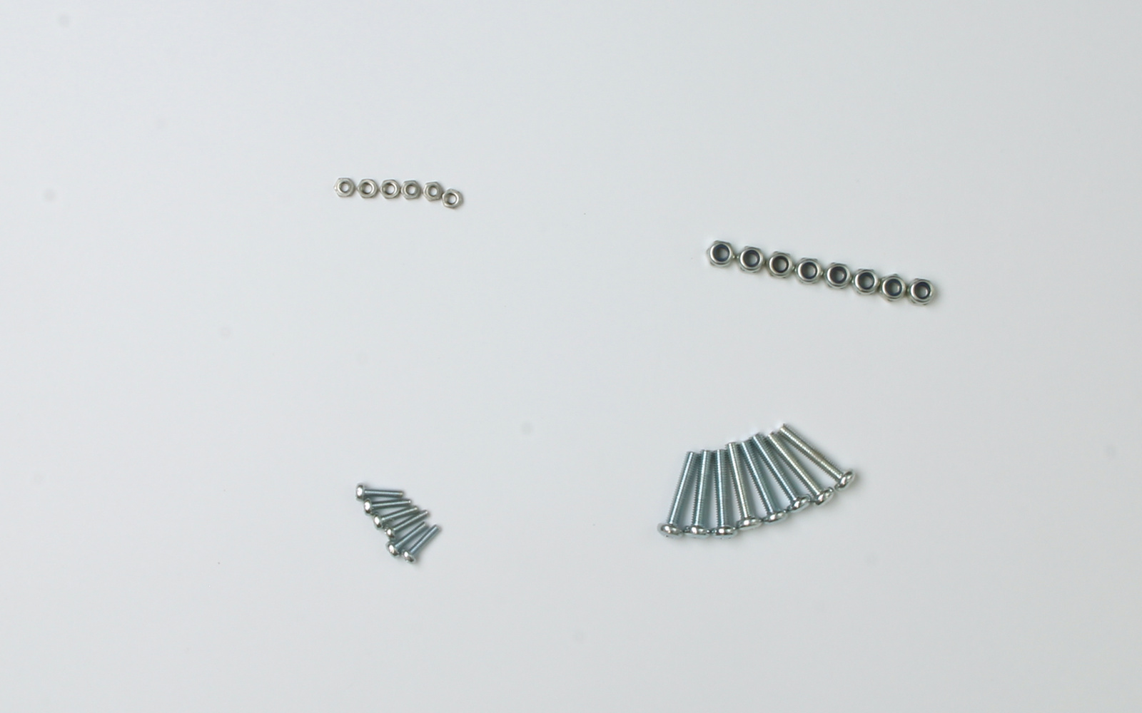
- 8 Pan head M3 15mm machine screws (a)
- 8 Hex Nyloc Nuts (b)
- 6 Pan head M2 8mm machine screws ( c )
- 6 Pan head M2 Nuts (d)
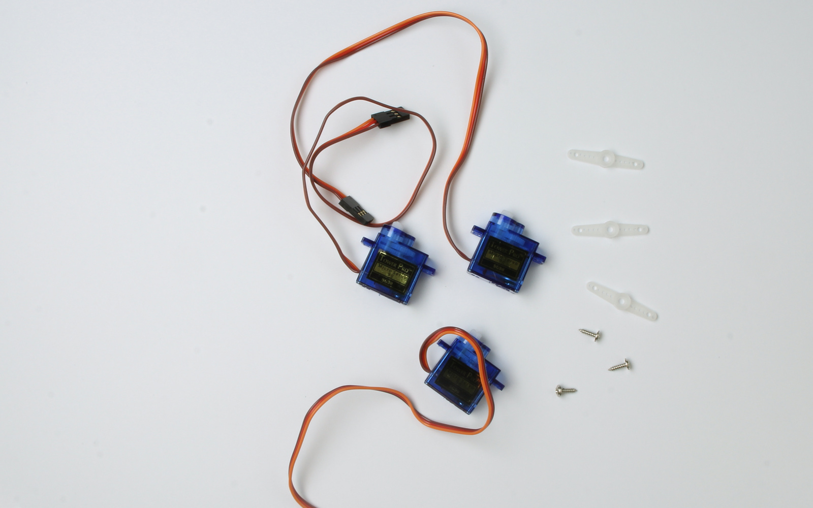
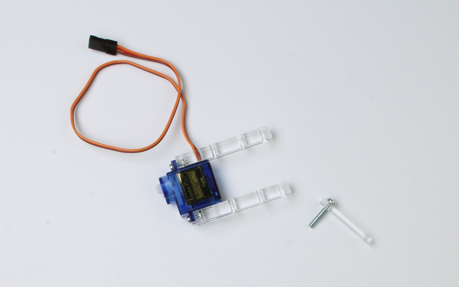
- 3 9g micro servo motors (e)
- 3 Servo Arms (f)
- 3 self tapping screws to suit servo motor arms (g)
- 1 Arduino Nano (h)
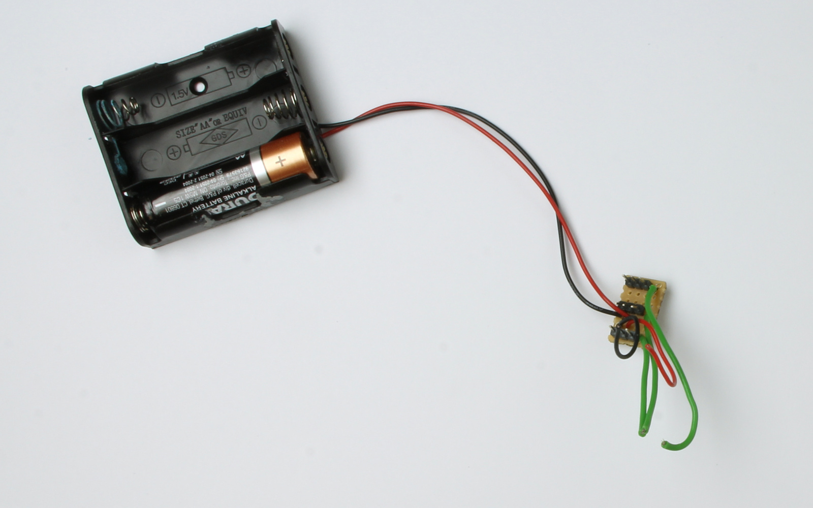
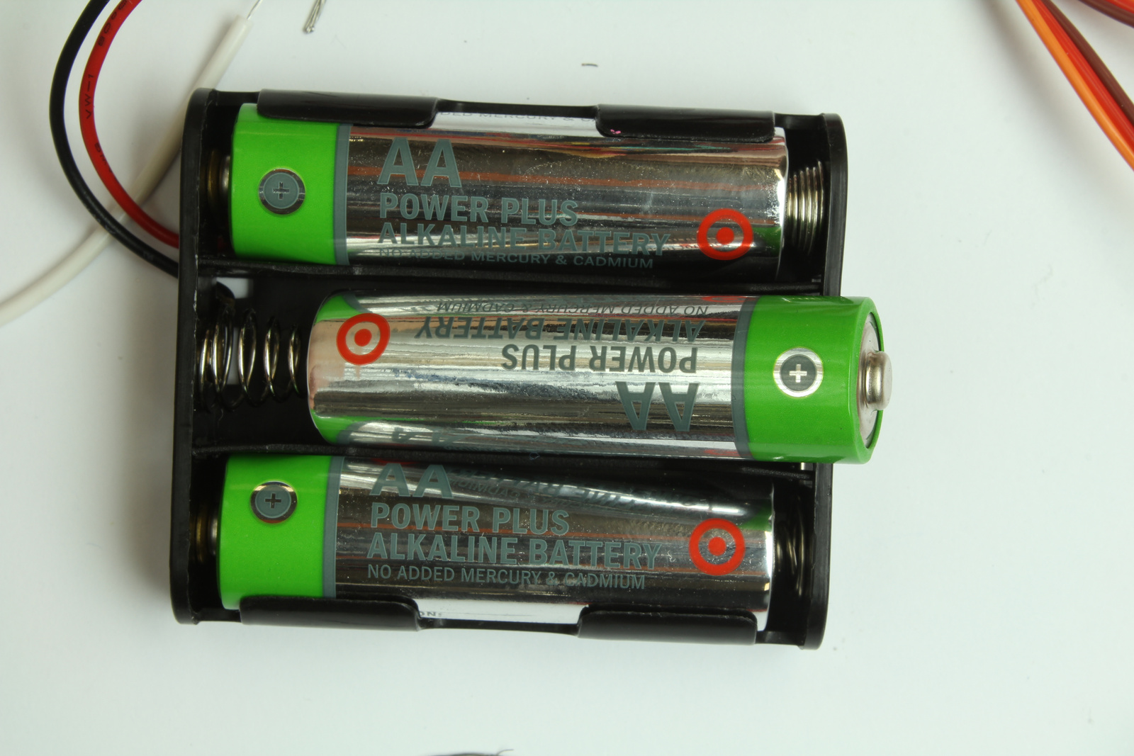
- battery holder for 3AA cells with adaptor board attached (i)
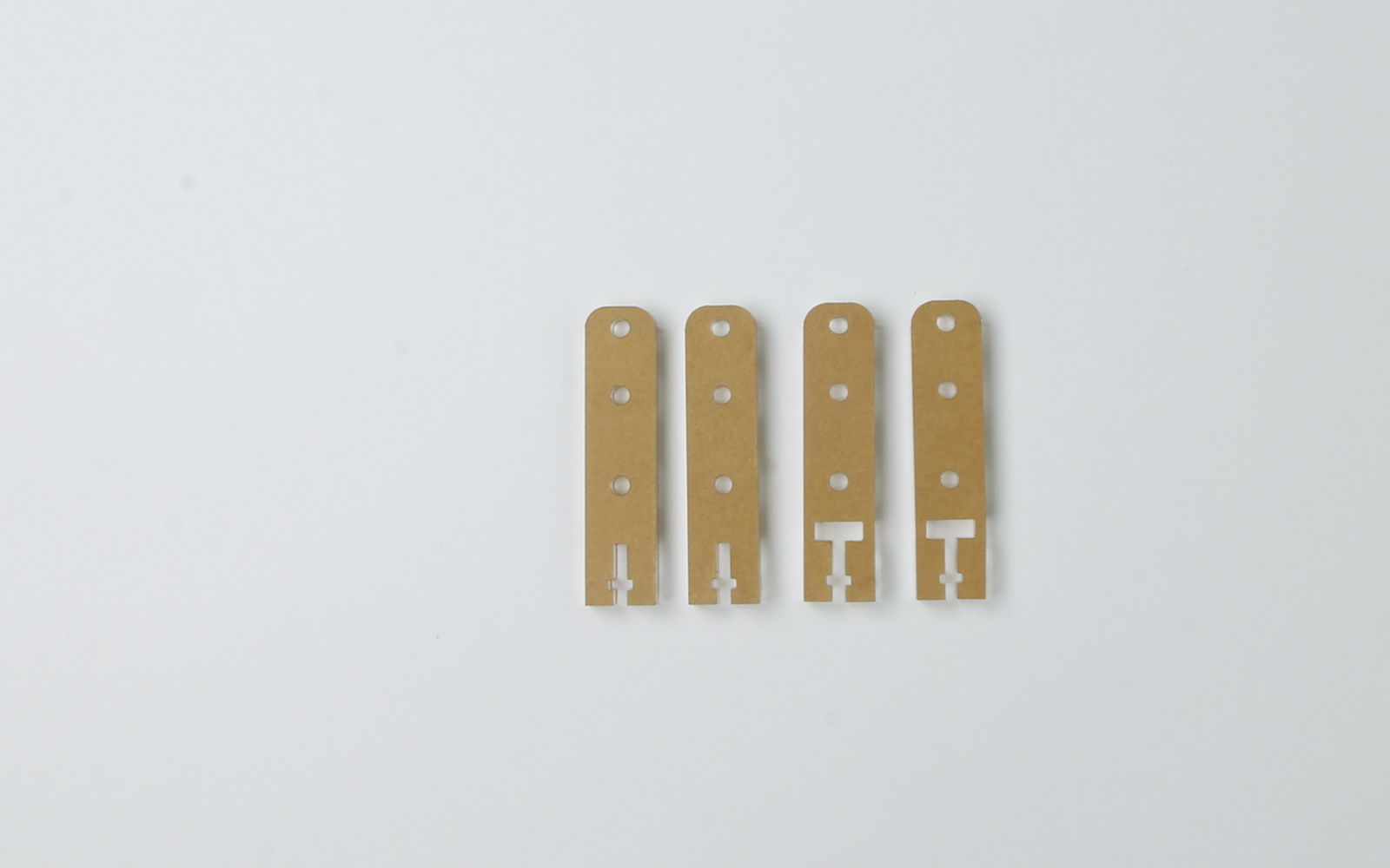
- 2 leg parts (type I - without slot) (j)
- 2 leg parts (type II - with slot) (k)
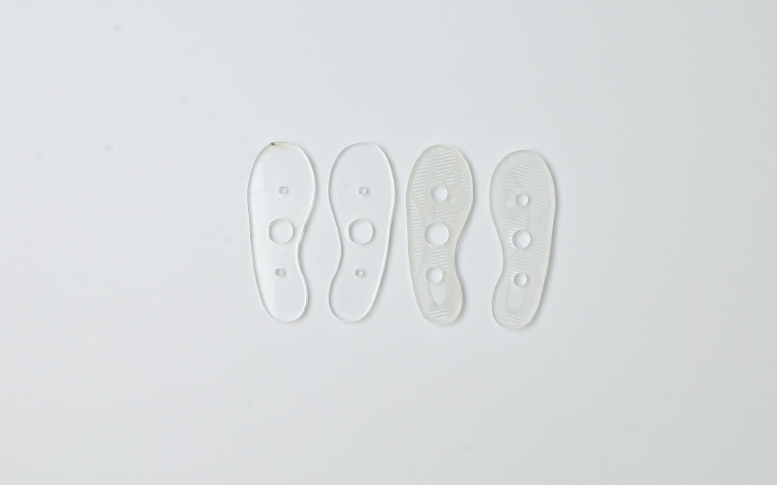
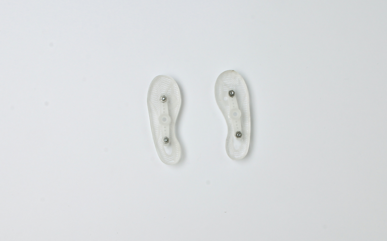
- 2 foot tops (l)
- 2 foot soles (m)
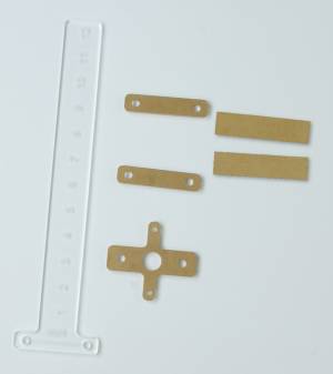
- one counter-balance shaft (n)
- two cross-pieces (with holes) (o)
- two braces (p)
- one servo mount (q)
Tools
- laser cut M3 spanner
- Philips head screwdriver
- Acrylic glue or Super Glue
- soldering iron and solder.
Instructions
Step One
Peel off all paper coating on acrylic pieces.

Step Two
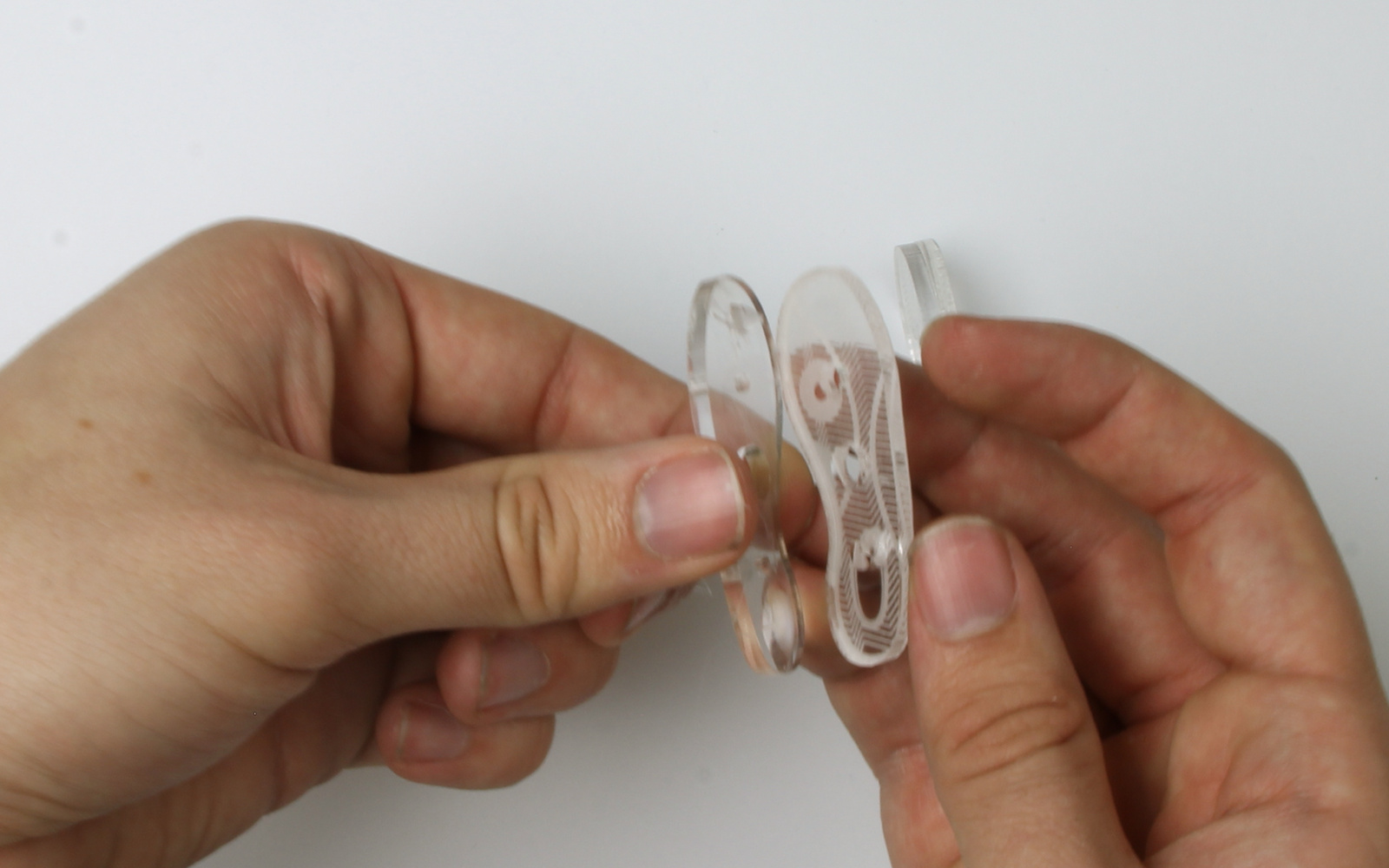
Glue the etched and un-etched foot shaped pieces (l + M) together with the etched side facing out.
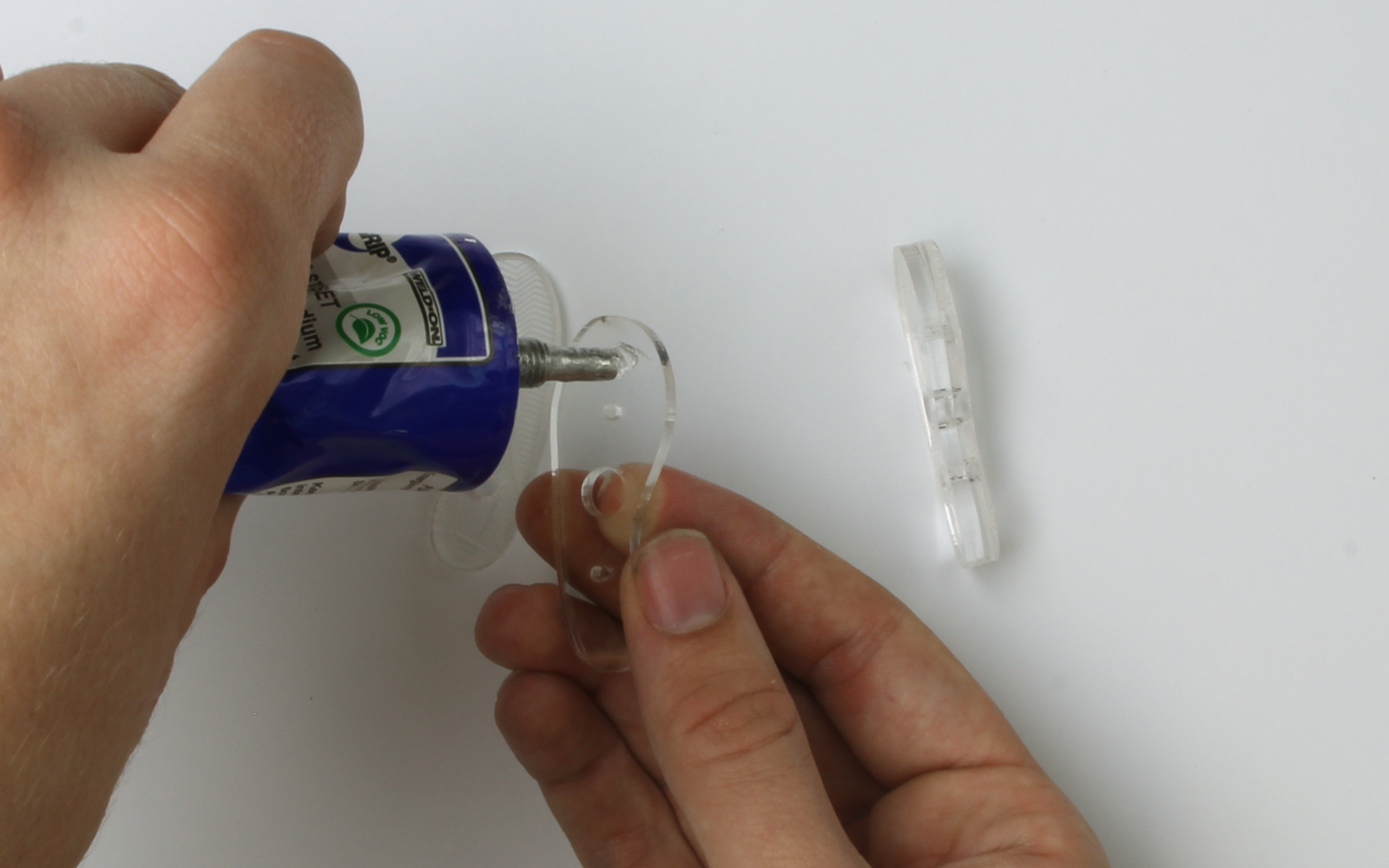
Repeat this process for the right foot, Note: the two un-etched pieces are identical.
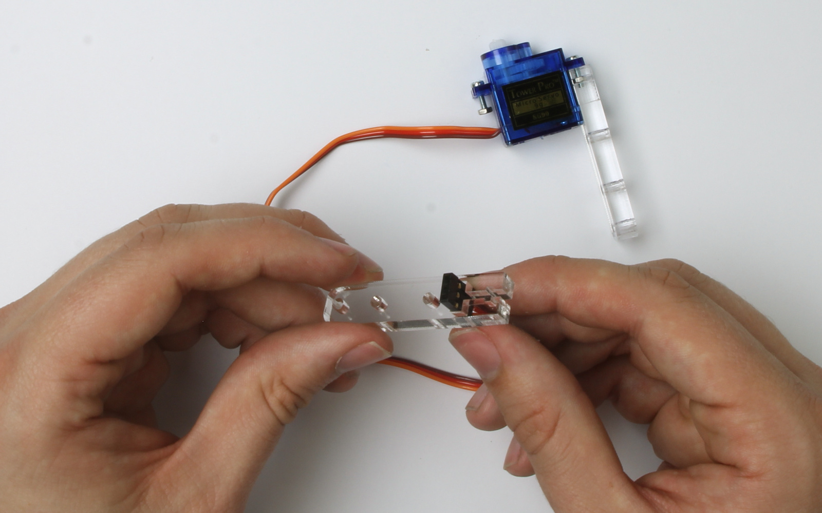
Step Three
Grab a servo (e) a insert a smaller M2 screw ( c ) on the side without the cord.
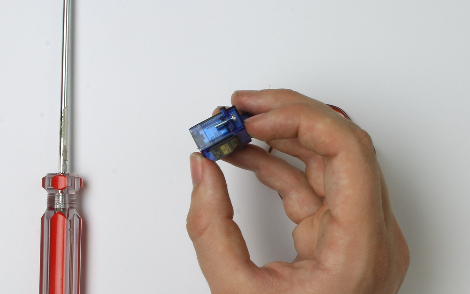
Loosely add a nut(d) so that the thread is just visible on both sides.
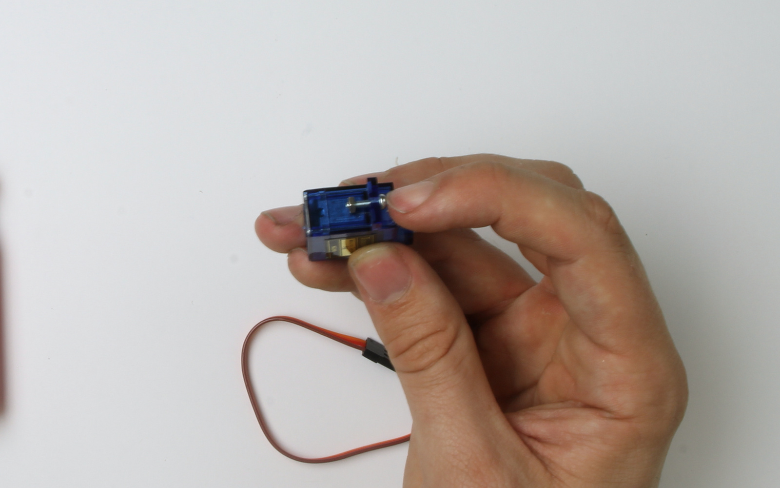
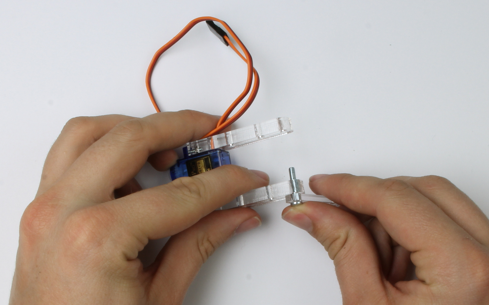
Slip one of the TypeI legs (j) over the screw and nut. This may require some jiggling as the nut must align to get into the hole.
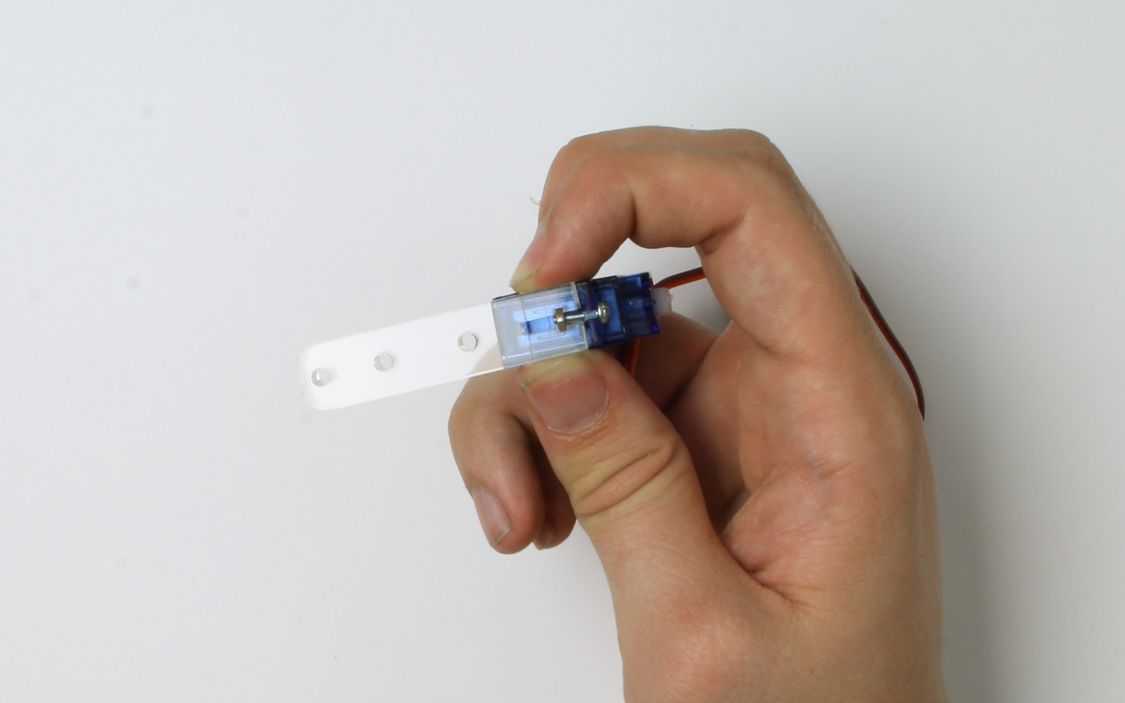
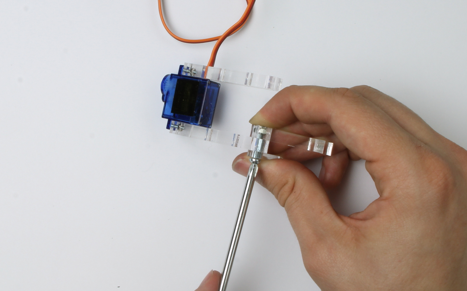
Tighten the screw until the nut is held in place.
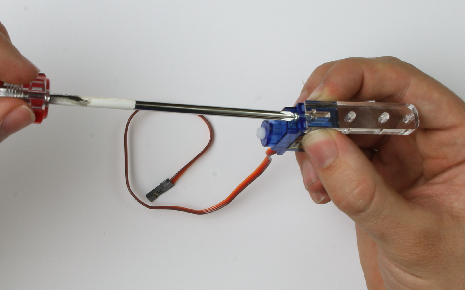
Repeat this process for the other side of the servo.
Take care to thread the electrical cord through the slot provided on the leg.
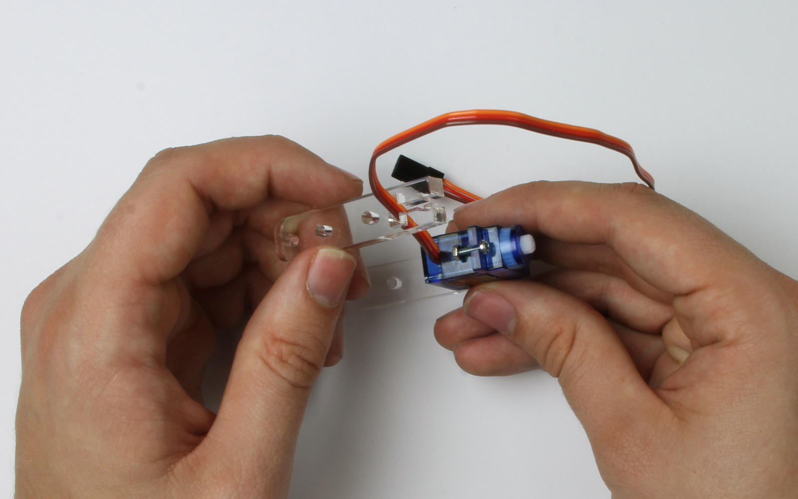
Repeat for the other servo.
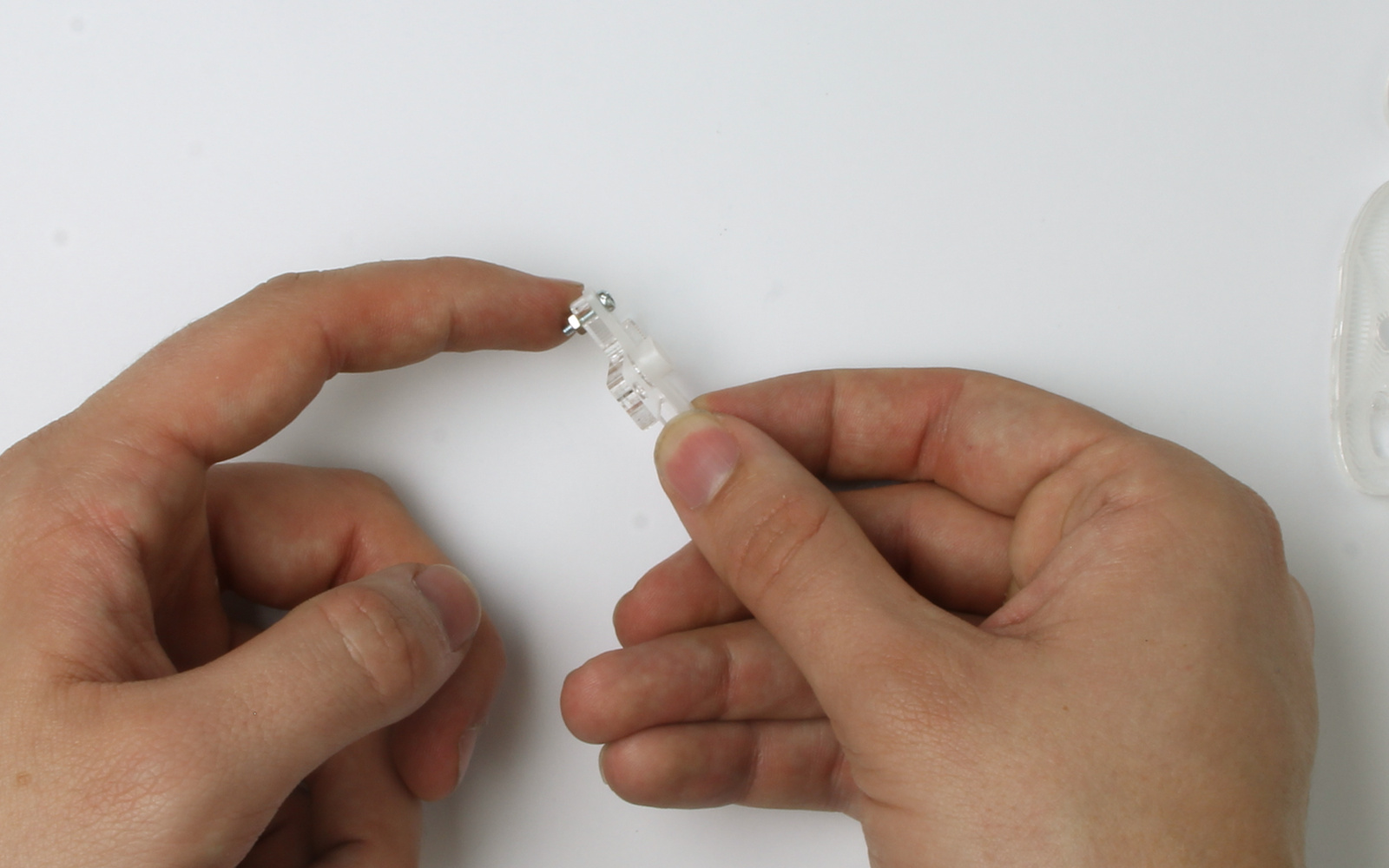
Step Five
Attach the nylon servo (f) arm to the servo (g) using a smaller screw ( c ) and nut (d). Make sure the screw heads are on the same side as the servo arm.
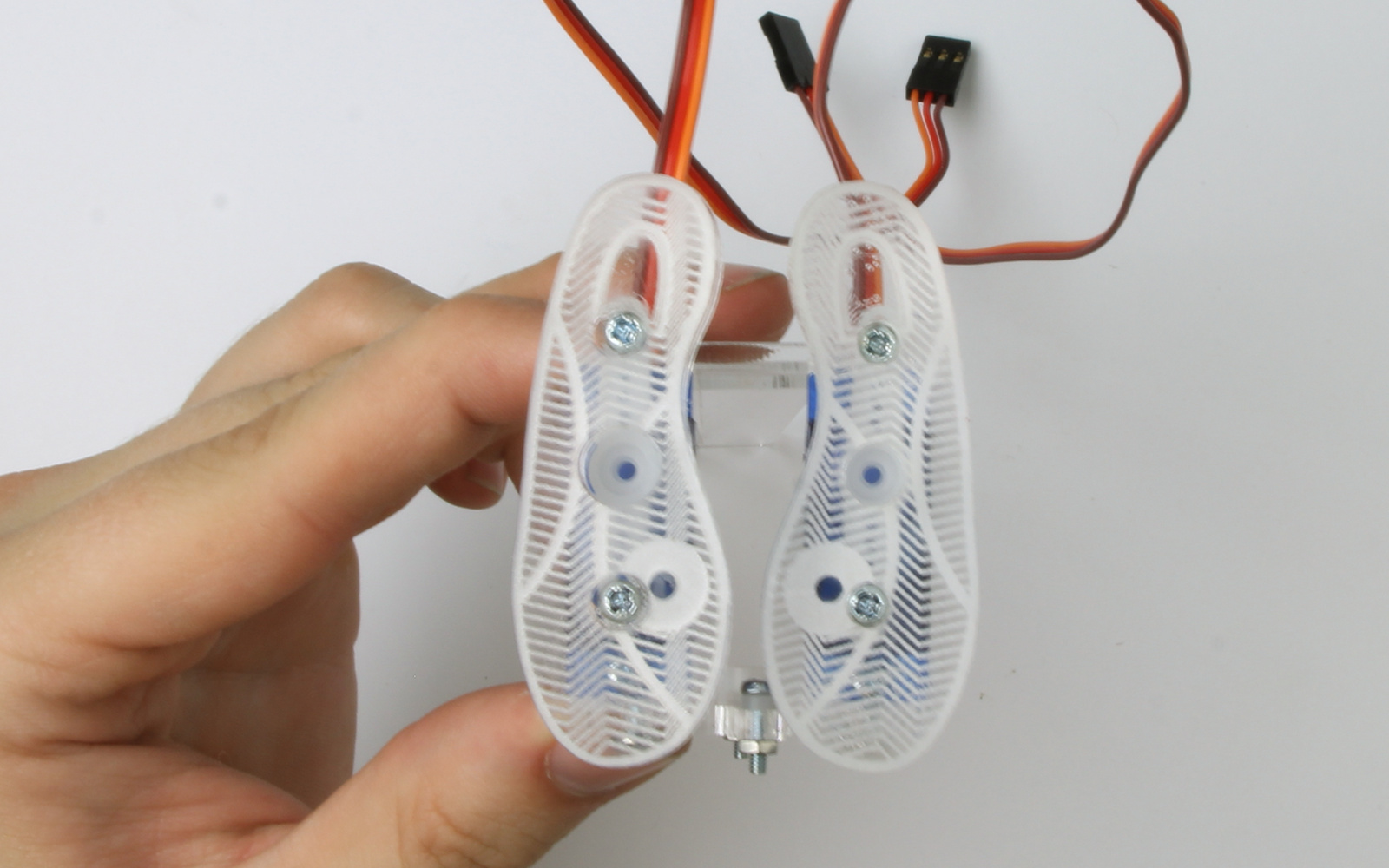
Push the screw all the way into the feet.
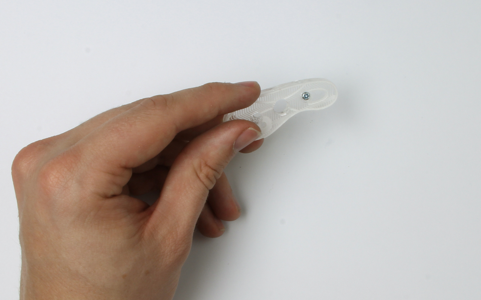
Attach the servo arm to the feet as shown below.
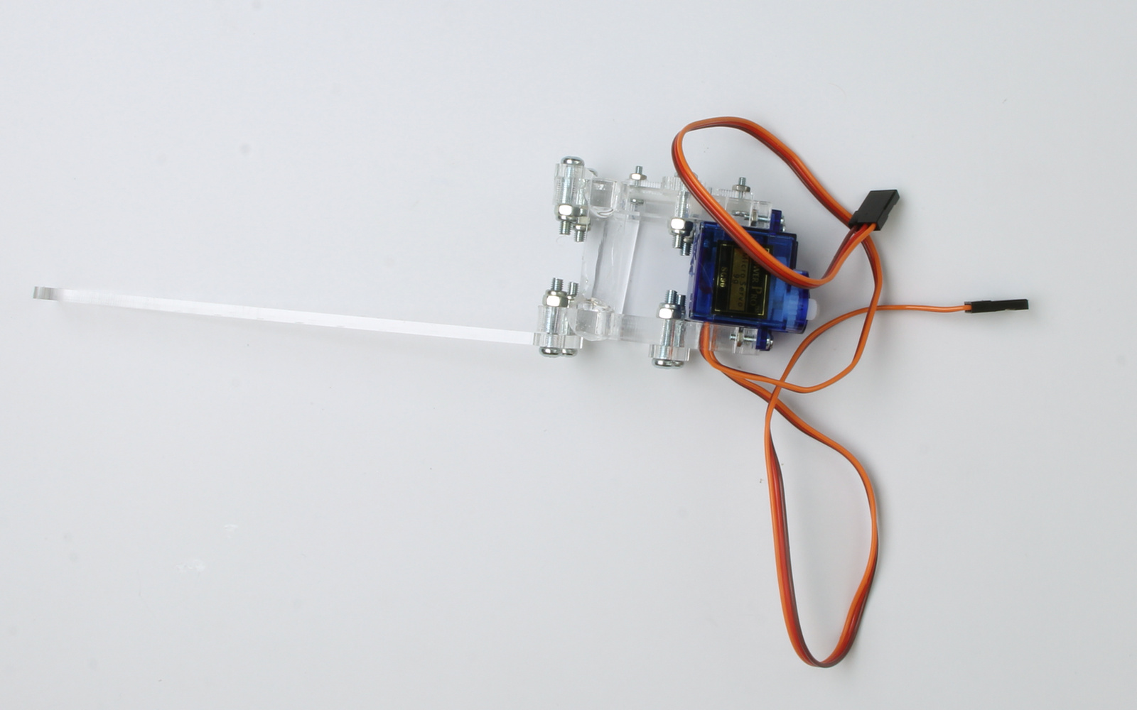
Step Six
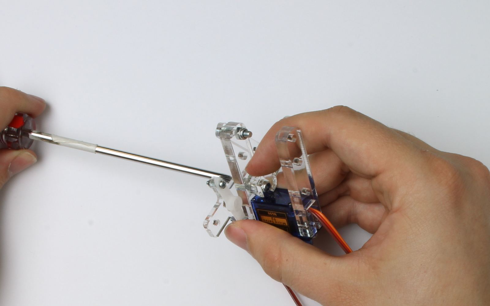
Put an M3 screw into a cross-piece.
Push the screw into the hole furthest from the leg, on the wireless side of the servo.
Add a nyloc nut and tighten using a screw driver and the small spanner provided.
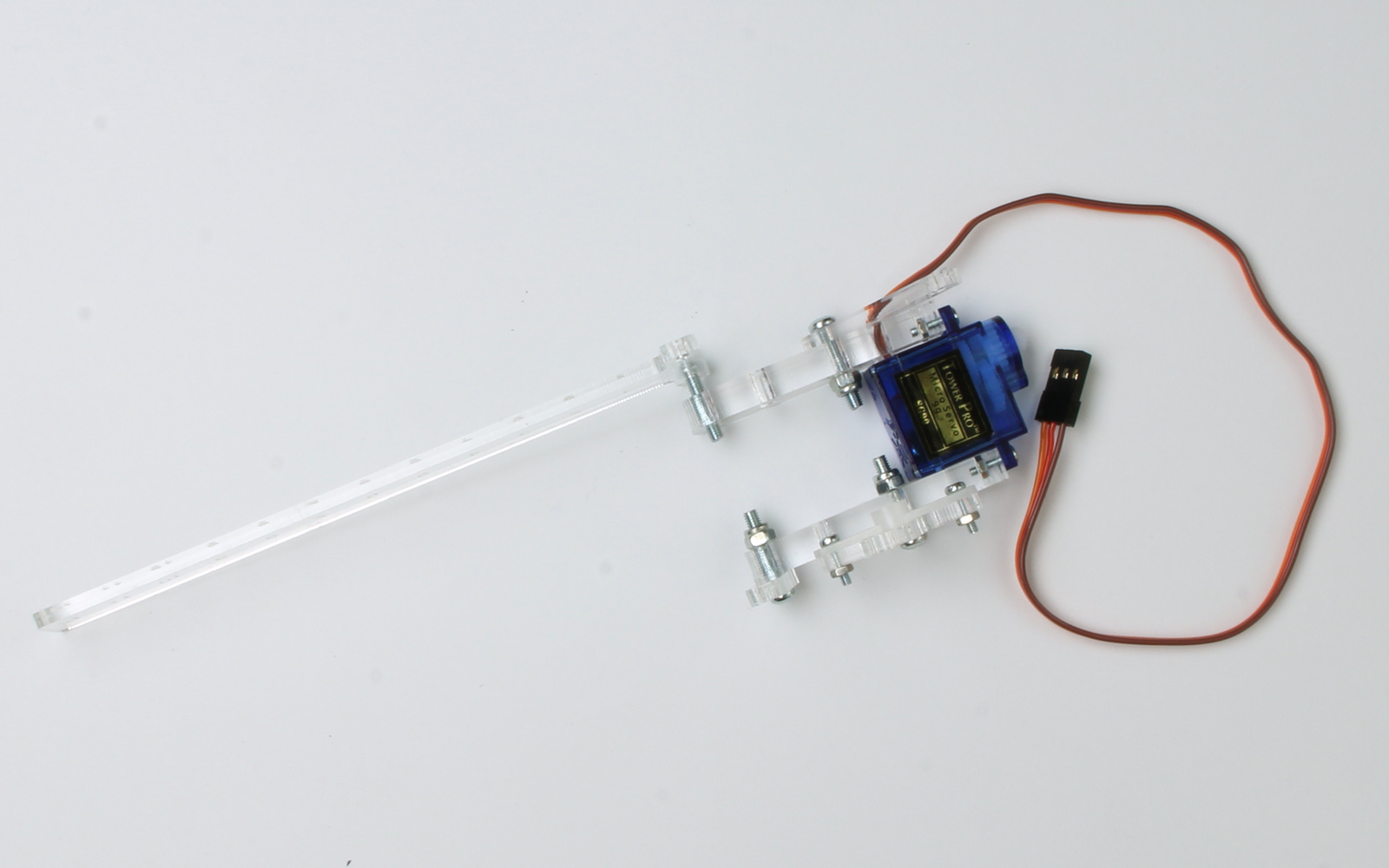
Fit the servo mount, with the servo arm facing inwards to the same leg.
On the other leg, attach a cross-piece to the hole closest to the servo.
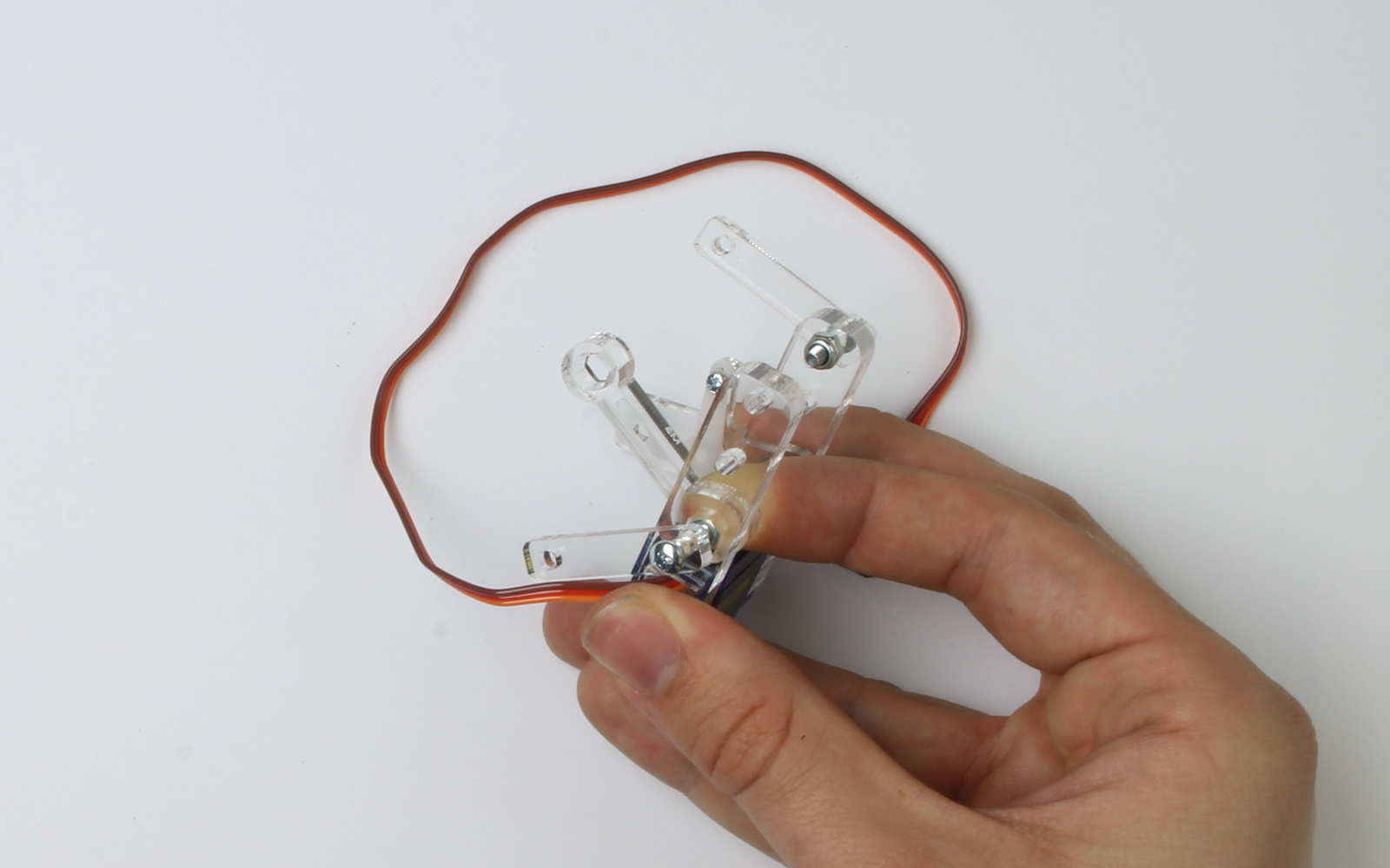
Fit the counter-balance to the last hole.
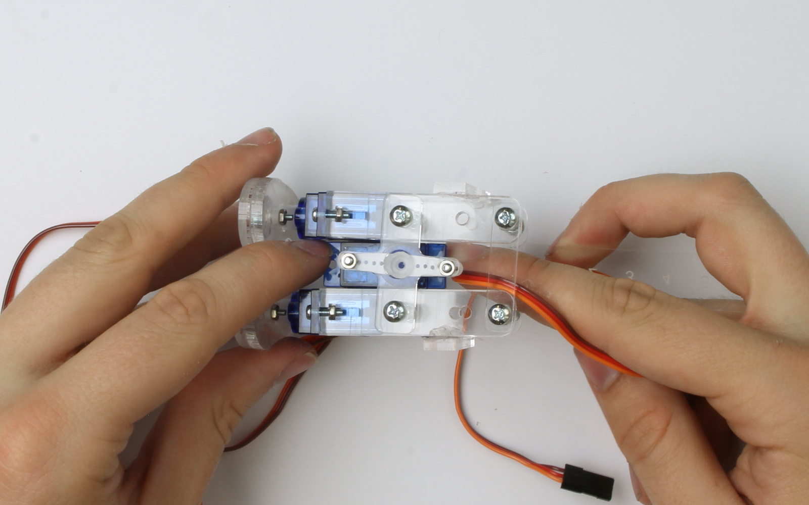
Its time to attach the second servo. Make sure the cord is on the same side, then mount it the same way.
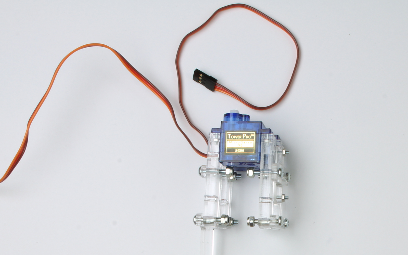
Glue the two braces across the legs for extra support.
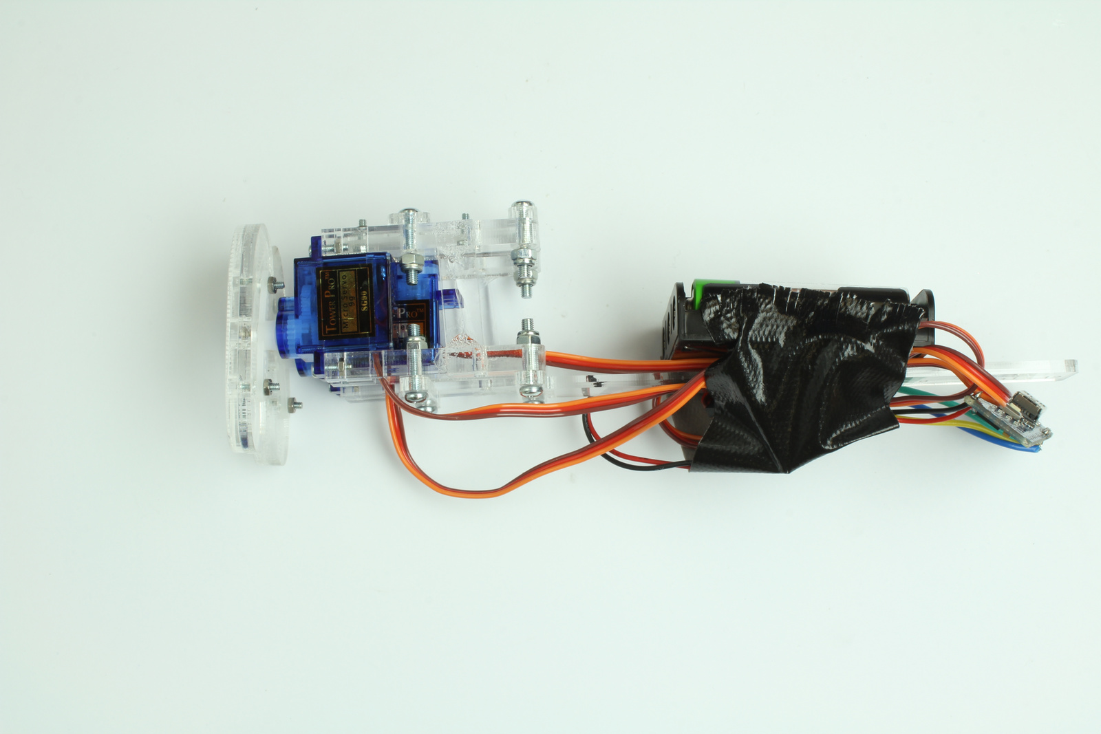
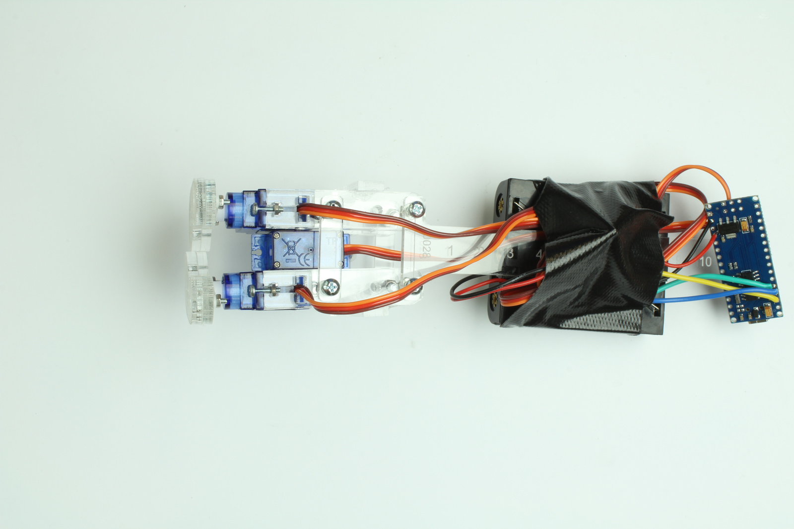
Step Seven - Electronics
Solder the three coloured wires to the arduino nano' connecting them to D9,D10,D11 on the arduino.
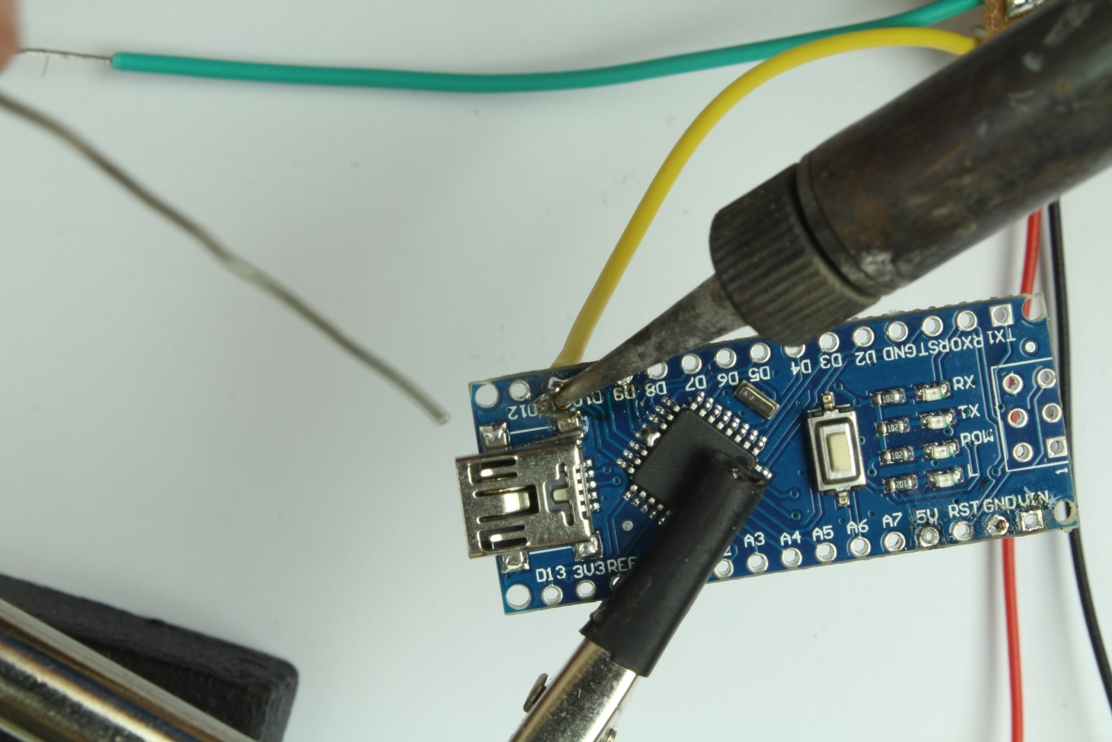
Trim off any excess wire.

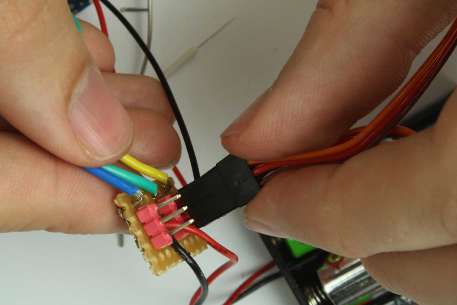
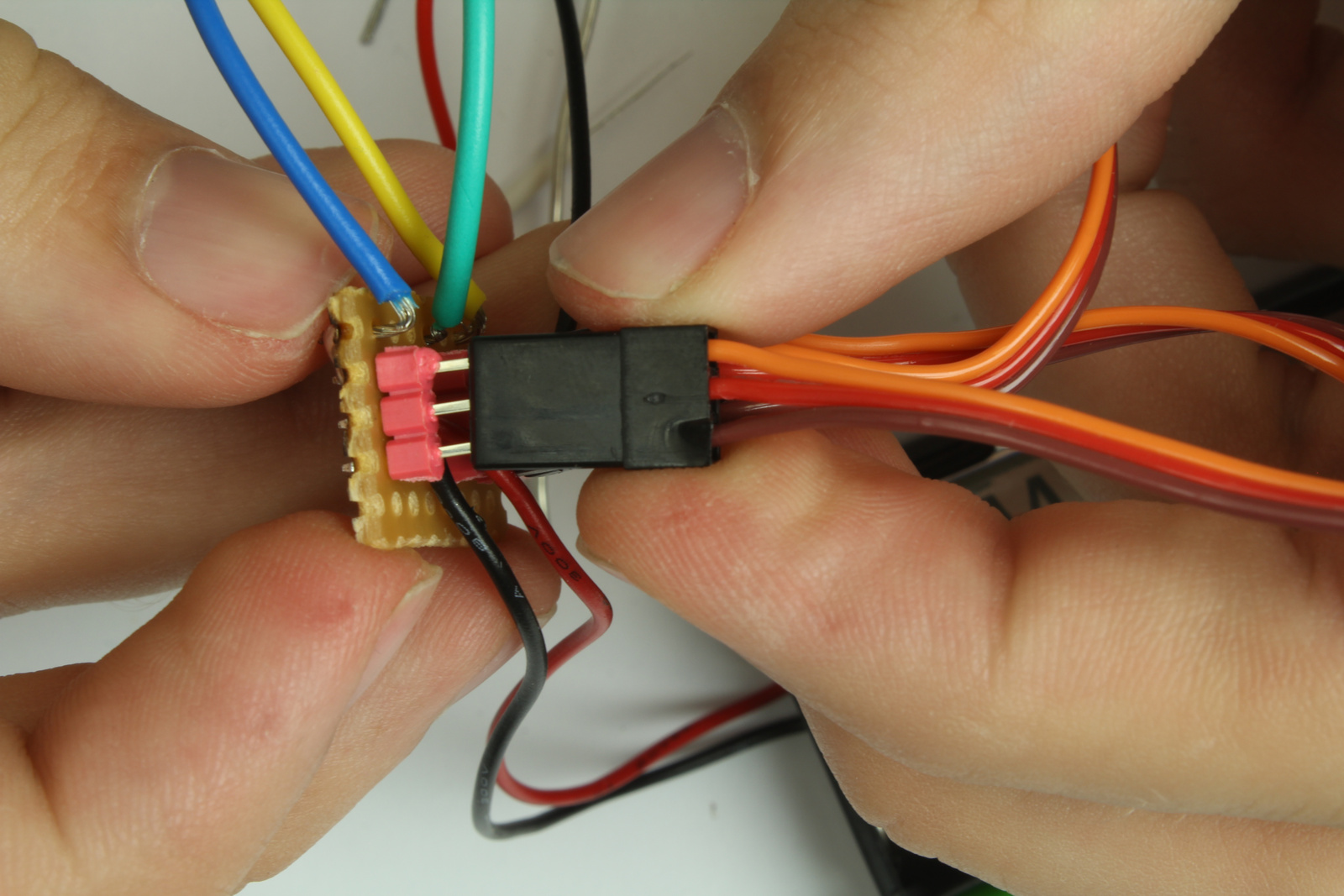
Connect the servos to the adaptor board headers. Take care to connect the brown wire from the servos to the black wire on the apdator board.
Make sure to connect the center servo to wire connected to D11 (in this case the yellow wire).

The legs move in sync so they both may be connected to either pin D9 or D10
Place the batteries into the battery holder briefly until the servo's move then stop.
This correctly aligns the servos for final construction.
Press and screw on the feet so they are aligned perpendicular to the servos.
Now the center servo can be attached. Try to keep the frame as square as possible
the battery holders boards and wires can then be taped to the counter-balance shaft.
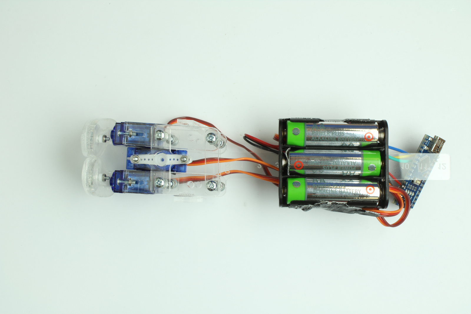
They act as a counter-weight. This may need some adjustment to find the optimum height.
<hidden>