Introduction to Surface Mount
Summary
- Demystify the elements and processes used in modern electronic assembly
- Remove fear of working with such parts by focus on practical skill and techniques.
- Build a small and pretty item that can be shown off.
- Workshop allows for mistakes and how to correct them.
Introduction
Surface Mount Devices
Surface mount devices are simply the current evolution of through-hole components. They are optimised for size and for automated 'Pick and Place' and as such come across as somewhat unfriendly to those used to traditional components.
Because they are intended to be machine placed and because the machines as well as demands of consumers continue to evolve, surface mount components can be extremely small and tricky to work with by hand. This project's smallest parts are based on 0805(Imperial size, approximately 2 by 1.2mm) components, a good compromise between ease of placing and current sizes used in electronics that are easily a quarter of this size.
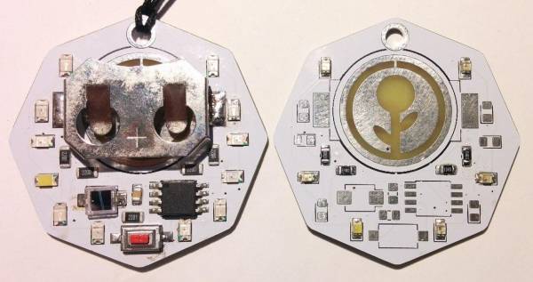
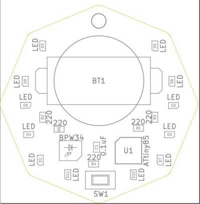
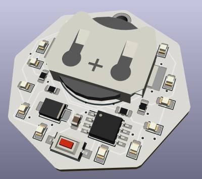
Rather than a simple board with The whole badge is based around an Atmel ATtiny85, 12 leds, a button and a light sensor.
Kit
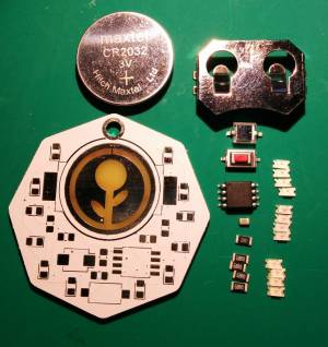
The basic kit includes:
- 1x Custom PCB
- 12x 0804 SMD LEDs
- 4x 0804 220Ω resistors
- 1x 0804 1kΩ resistor
- 1x 0804 0.1uF Capacitor
- 1x SOT-8 ATTiny85-U10
- 1x BPW34 light sensor
- 1x Switch
- 1x CR2032 Battery holder
- 1x CR2032 Battery
- 1x Lanyard
Equipment
Tools
- Tweezers
- Magnifying devices
Consumables
- Solder paste
- Solder
- Flux
- Isopropanol (For cleaning)
- Braid (For fixing mistakes)
Instructions
Order
Doing the hot air components first makes things easier. Hand soldering is more accurate but trickier.
Hot air
Set the hot air station to 350°C, test that it comes up to temperature when lifted off it's stand and that it returns to cold when returned. Setting the 'Air' knob to he lowest setting will prevent parts from being blown away.
NOTE: These stations have a 'cool down' function that keeps the fan running until the head is below 100°C to protect the elements. It will turn off automatically.
The parts to be installed at this stage are:
- Micro
- Sensor
- Cap
- 1kΩ resistor
- Every second LED
To each pad apply a small amount of solder paste and then place each component with a pair of tweezers.
The micro, sensor and LEDs all need to be placed the right way around.
Hand solder
These components are either easier to solder by hand or have been chosen to allow practice.
- Switch
- Battery holder
- 220Ω resistors
- Rest of the LEDs
Tin the one side of the pad with a small amount of solder.
Development notes
Feedback
References
Files
This is where you put files for laser cutting, Excel sheets of suppliers etc..


