Animatronic Snow Globes

This workshop was developed for Christmas 2020 by Peter Musk
Acknowledgement
We acknowledge Aboriginal and Torres Strait Islander peoples and their continuing connection to land and as custodians of stories for millennia. We respectfully acknowledge the land on which we all meet today, and pay our respects to elders past, present and emerging.
Summary
Snow Globes found immediate popularity after their invention in Austria in the late 19th century, and have been used as decoration, art, advertising and memorabilia ever since. While traditionally snow globes were filled with liquid, and required human effort to set the contents in motion, more recent examples have used electronic and mechanical means to produce a changing scene.
In this workshop, a hacked servomotor, magnets and a bespoke gearbox are integrated with a commercially available glass dome to allow workshop participants to construct an animated scene of their own devising. While magnetic coupling allows the transfer of motion into a liquid filled display without risking leaks, a simpler version is also described if liquid is not required. More complex versions adding arduino controllers and LED light or sound effects could also be built on this standard format.
Safety Warning
The Law About Using Magnets in Toys
In Australia (and many other countries in the world), the use of small, powerful magnets in toys is banned.
Ingestion of these types of magnets by small children has led to hospitalization, and death (and ruinous law suits for the makers). Small, powerful neodymium magnets can still be used for other purposes, but use in toys (even desktop toys, and even when embedded) is specifically prohibited. In this workshop, legislative requirements have been addressed by using magnets large enough to fall outside the definition of 'small' - basically magnets too big to be easily swallowed. Check the legal conditions that apply in your jurisdiction before reproducing this workshop, for the safety of others, and yourself.
Skills Introduced
- soldering and simple circuit building to hack the servo and switch
- hand tool use in the assembly of motorised gearboxes from laser cut parts
- creative application of laser cutting and 3D printing to devise scenery
- perseverance and problem solving designing and assembling the device
Materials
| Material | Quantity | Cost | Supplier |
|---|---|---|---|
| Glass dome (dia: 98mm, height: 190mm) | 1 | $9.90 | Ikea # 203.444.31 |
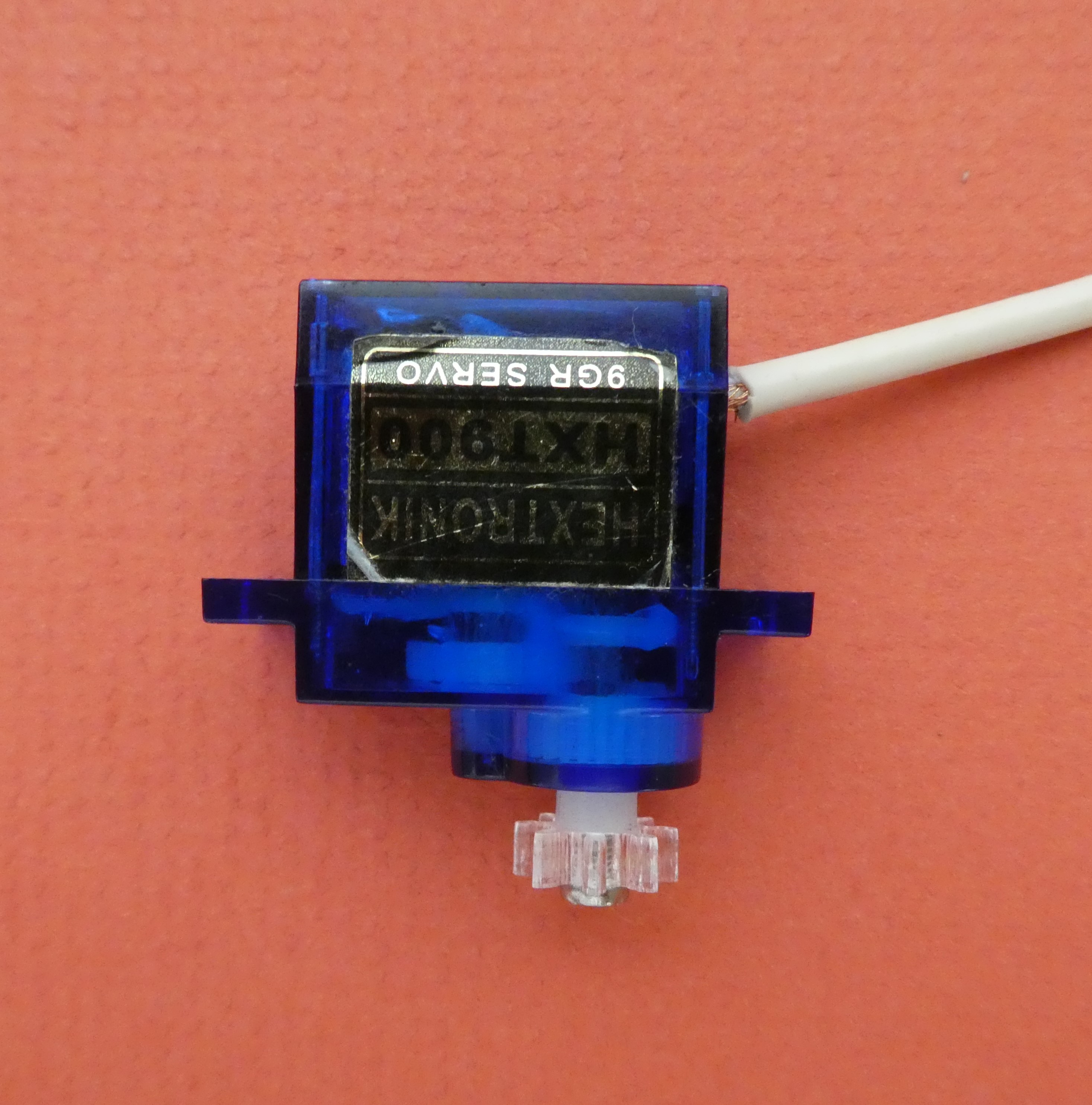
| 9G servomotor | 1 | $3 - $11.00 depending on source | electronics or hobby suppliers |
| Jumper wires (1 each M/M and F/F) | 2 | 30c ea (60c total) | electronics or hobby suppliers |
| Ferrite disc magnet (31.75mm dia) | 2 | $1.30 ea ($2.60 total) | Frenergy Magnets (Australia) |
| Acrylic sheet (3mm and 1.5mm) | 1 x A4 | $3 - $5.00 depending on source | online acrylic sheet suppliers |
| M3 x 30 panhead screw | 3 | 7.5c ea (bulk) (22.5c total) | Fastener Factory |
| M3 nuts | 3 | 1.5c ea (bulk) (4.5c total) | Fastener Factory |
| M2 x 6 panhead screw | 1 | 3c ea (bulk) | Fastener Factory |
| M2.5 x 10 panhead screw | 4 | 3c ea (bulk) (12c total) | Fastener Factory |
| M2.5 nut | 4 | 3c ea (bulk) (12c total) | Fastener factory |
| M12 flat steel washer (25mm dia) | 2 | 11c ea (bulk 22c total) | Fastener factory |
| 8G x 10mm panhead self tapping screw | 2 | 1c ea (in bulk) (2c total) | Fastener Factory |
| 7mm dia x 200mm rigid irrigation riser (black) | 1 | 95c ea | Bunnings |
| 2.85mm dia 3D printing filament | 100mm | 50c | scrap |
| USB cable | 1 | recycled | e-waste (keyboards) |
| SPDT sub-min slide switch | 1 | 80c depending on source | electronics supplier |
| 3mm heatshrink tubing | 10-15cm | 15c | electronics supplier |
| 110mm dia PVC pipe | 70 - 130mm | 90c ($9.00/m) | Bunnings |
| Total | $26.54 |
Tools and Preparation
Preparation is partly dependent on the time available for the workshop. If run in a single session, participants will only have time to assemble and decorate the globe. In this case, the facilitator will need to have servos ready for installation, and probably have some decorative elements on hand.
If two sessions are available, then having participants hack the servo becomes the work of the first session. This allows introduction of basic soldering, and gives a better insight into how gearing is used to reduce rotation speeds. The almost guaranteed success also encourages participants to persist, and gives confidence for future use of soldering and electronics. The delay before the second session gives participants time to imagine, investigate and create the decorative elements to be installed, and then the final session is for assembly of the working globe. This can be used to introduce aspects of 3D printing or laser cutting design to the attendees.
Tools
- multitool screwdriver kit (with 000 Philips driver)
- side cutter
- wire stripper
- boxcutter
- soldering iron and solder
- hot glue gun
- saw (for cutting PVC pipe) A drop saw and clamps give the best chance of straight cuts.
- drill and bits (6mm and 2mm)
- sticky tape or electrical tape (to hold pieces for gluing)
- superglue (and releasing agent)
- clear silicone sealant (if liquid filled)
- access to hot water (preferably boiling), and a container at least 75mm deep.
Access to a laser cutter and/or 3D printer is preferred, though this work can be outsourced if time and budget permits.
Preparation
Before the workshop you will need to have kits of laser cut gearbox parts ready to assemble. Each kit also requires a single 3D printed gear (design files below).
Scrap e-waste with suitable USB cords will be required for each participant (or you can buy the wire and terminals, and assemble them as part of the workshop).
Examples of decorative elements made on a laser cutter or 3D printer are helpful to provide inspiration (some examples in Design Files below).
Workshop Walk through
Step 1 : Hack the Servo
Standard mini-servos (like the 9G example used here) are designed to have their speed electronically controlled, and never to make a full rotation. The first constraint involves having a miniature PCB inside the servo, and a couple of extra wires that carry the control signals. The second constraint involves having a physical stop in place on one of the driving gears inside the servo. Both of these constraints will need to be removed for the servo to rotate continuously under control of a simple on/off switch for this project.
WHY?
Continuous rotation servos are available (and these will not have the physical stop in the geartrain), but a speed control PCB will still be present. Speed control of mini-servo motors using electronic means (PWM, for example) is possible, but this will reduce the motor torque. Since maximum torque will be needed to rotate the most decorative elements possible, the approach here was to make torque a priority.
Sub-Step 1-1: Remove the servo PCB
There are 4 very small screws in the base of the servo that hold it together. You will need a 000 Philips driver (common in multi-tool kits) to avoid damaging the screws.. You might also need to remove or cut any stickers on the side of the servo that prevent the parts from being separated. You will probably find that the case surrounding the servo is in 3 parts, with the bottom giving access to the motor, and the top holding the geartrain.
DON'T DROP THE TOP!
When you undo the screws, and separate the parts of the case, be careful that the small geartrain is not catastrophically disassembled. Hold down the top of the servo as you gently remove the bottom, and maybe use a piece of stickytape to hold this in place as you work on the motor. You will need to fiddle with the gears later, but they are usually only held in place by the case, and come off their axles easily.
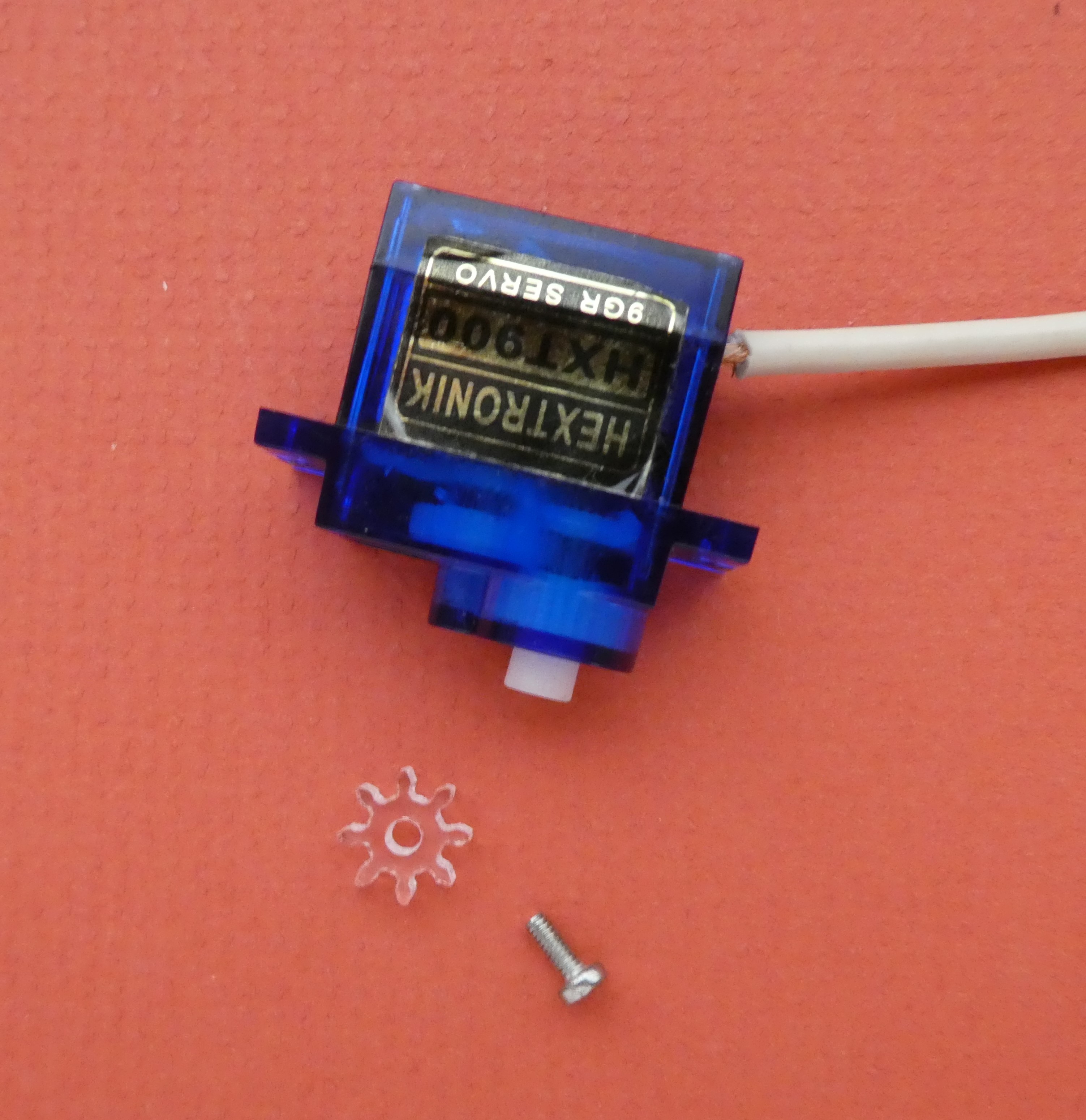
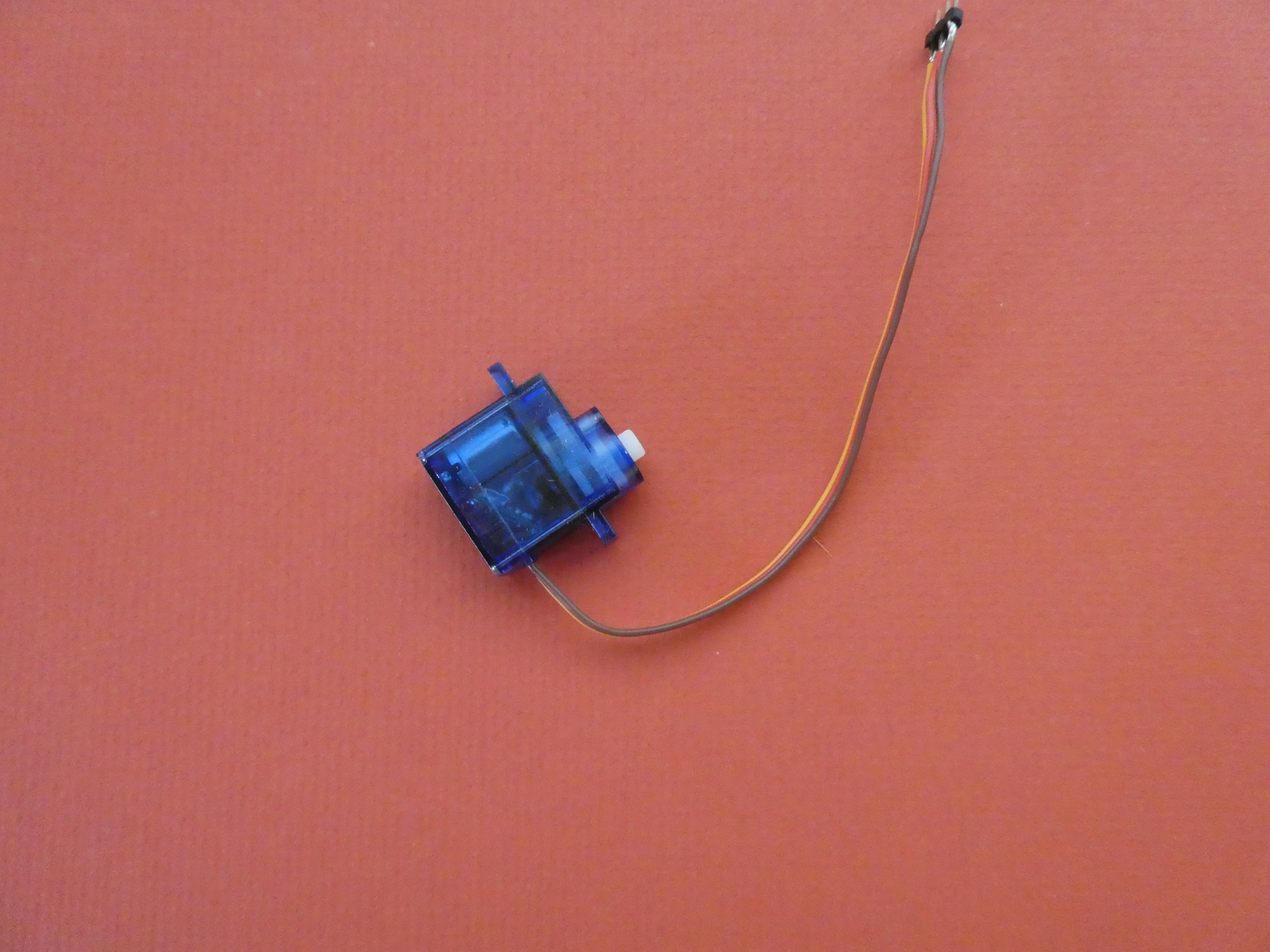 A standard servo
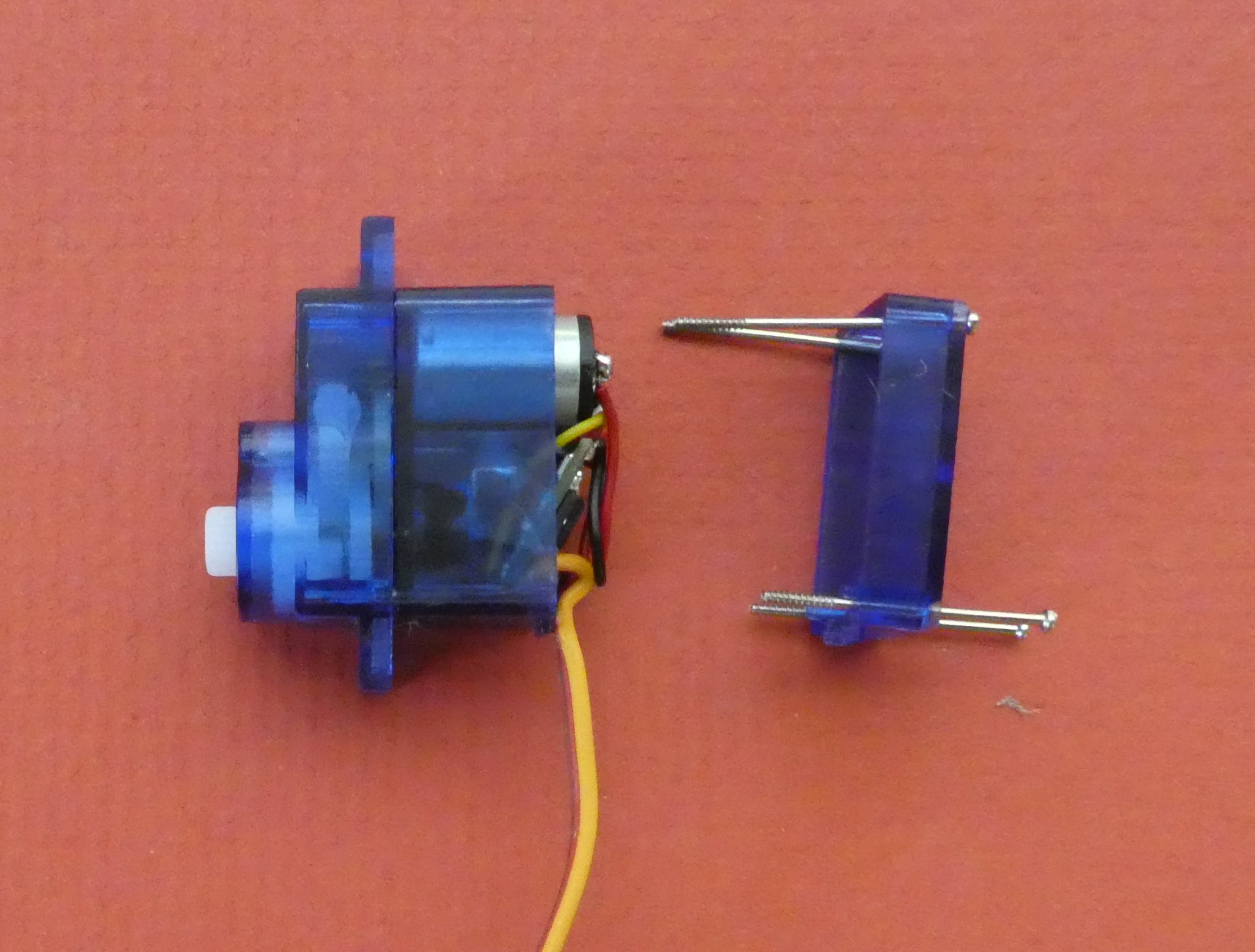 Remove the screws holding the case together GENTLY
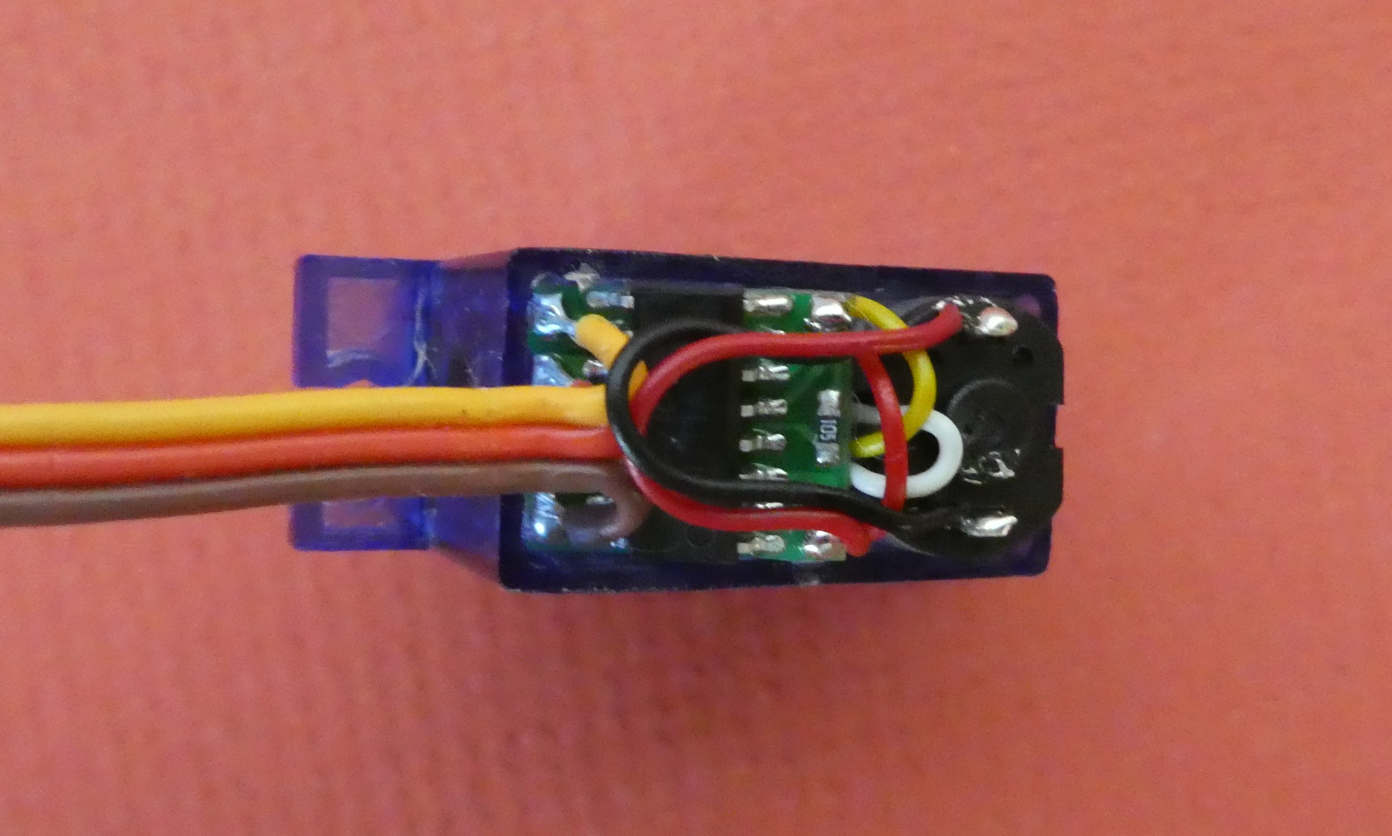 Inside the base where the PCB is located
 This is the PCB you are looking for.
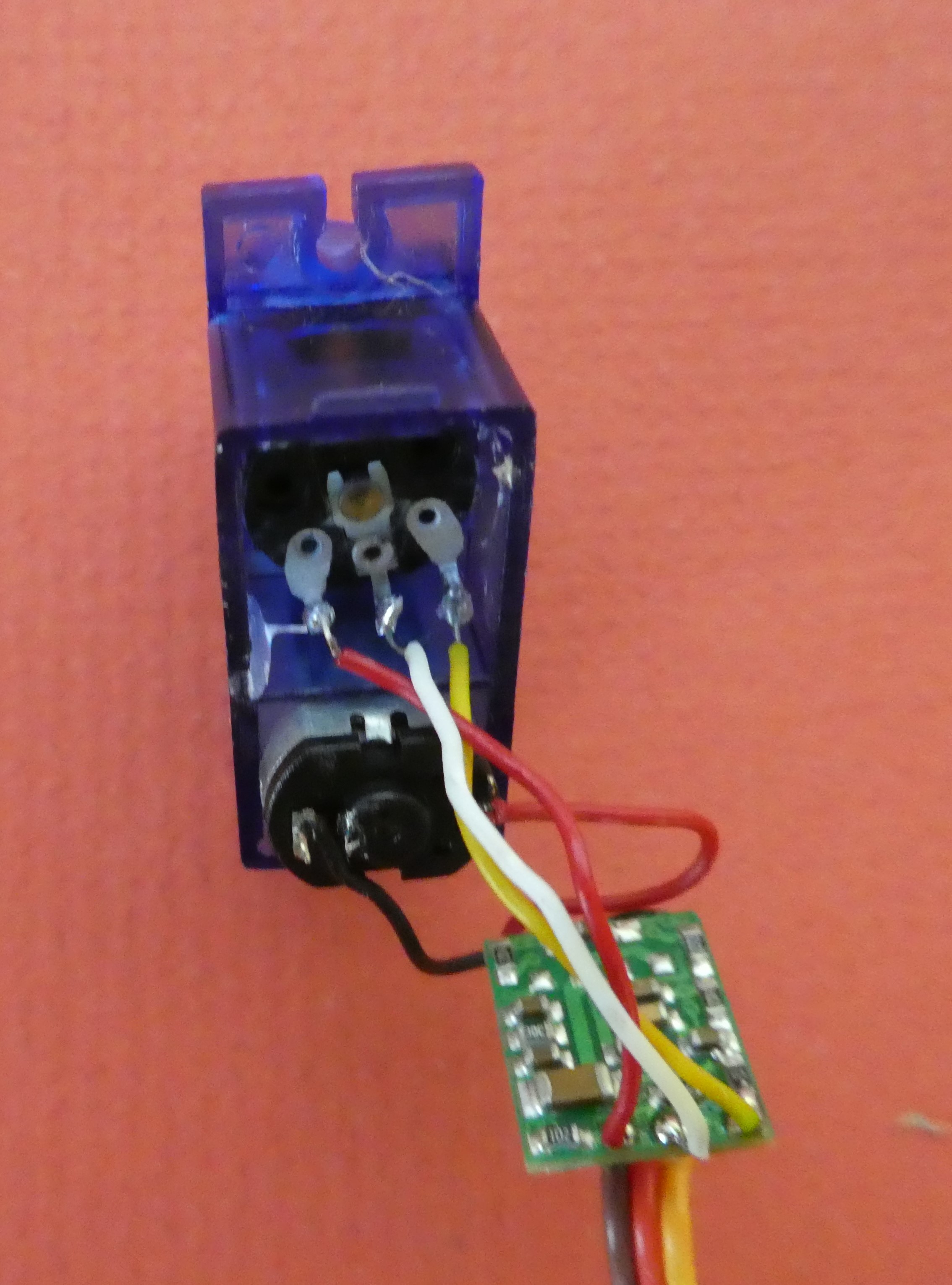
Now you need to desolder the PCB and remove it. You can see the terminals that need attention buried deep in the servo.
Leaving the wires attached to the motor will help maintain correct polarity when you add a USB connector later, so you can cut them instead (but desoldering them is OK too).
WHY?
Maintaining the polarity of the motor means you can decide the direction of rotation of the stuff you build inside the snow globe. Most servos will rotate clockwise, so reversing the polarity (attaching a red wire where the black wire is now, and vice versa) will reverse the direction of rotation. Of course, if all you want is motion, it does not really matter, and to decide in advance the direction of rotation you will have to think about how rotation changes through the gear train, too
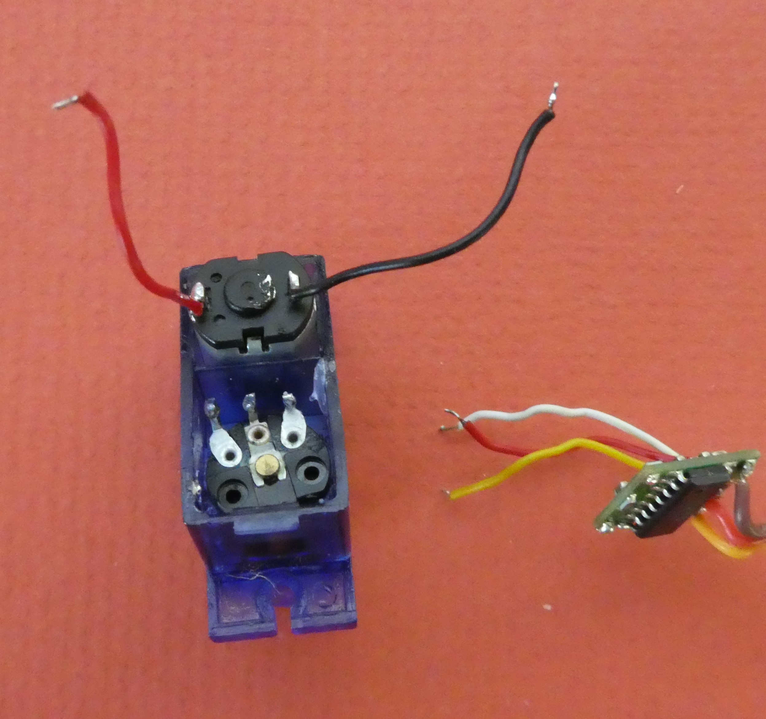 Remove the PCB and attached wires after desoldering
Sub-Step 1-2: Remove the stop in the gearbox
To work on the gears, you need to gently remove the top of the casing. The gears are located on very small shafts (and a bit of grease might be about the place, too).
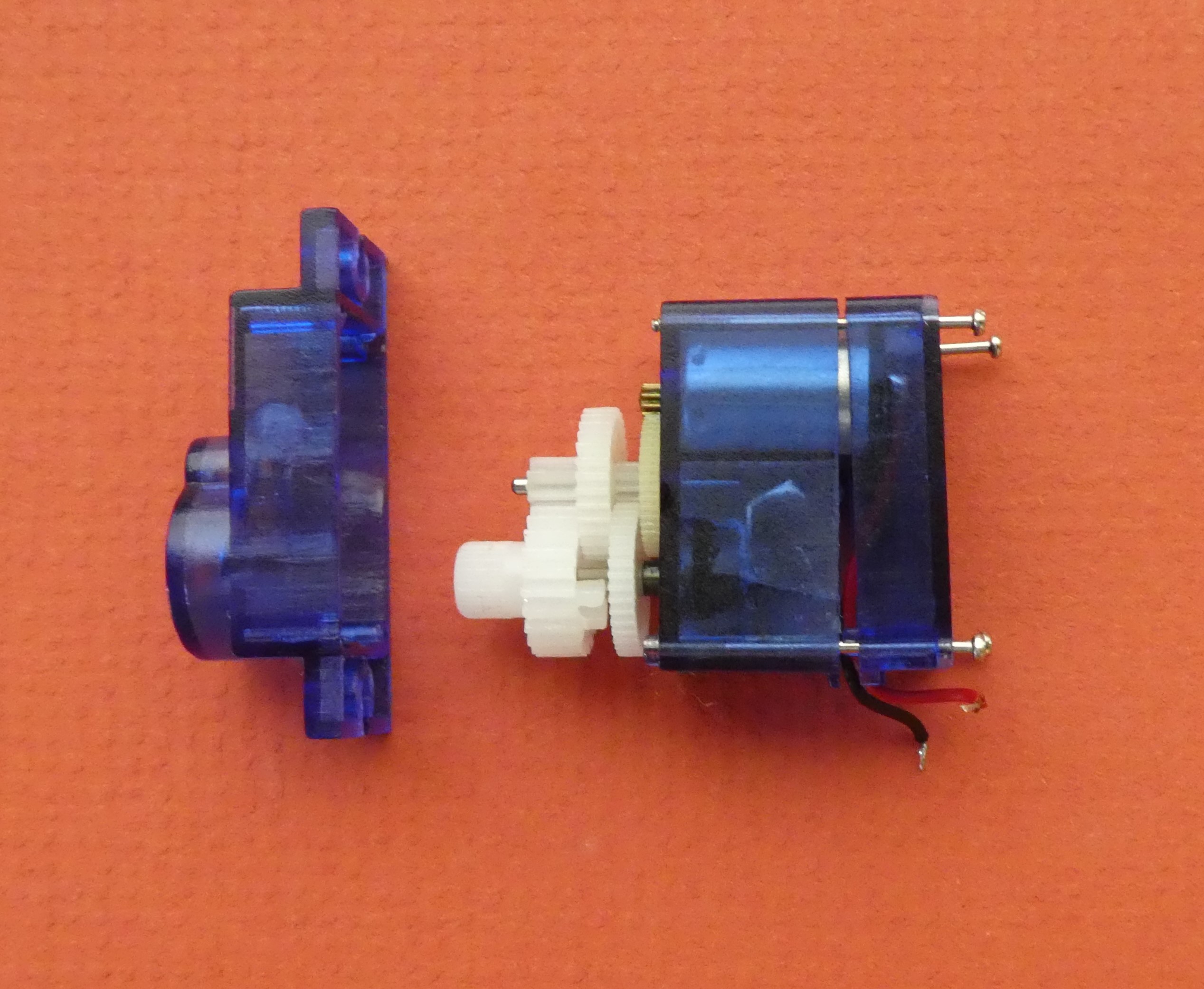 The topmost gear is the one with the stop.
![]() You can see the stop here.
You can see the stop here.
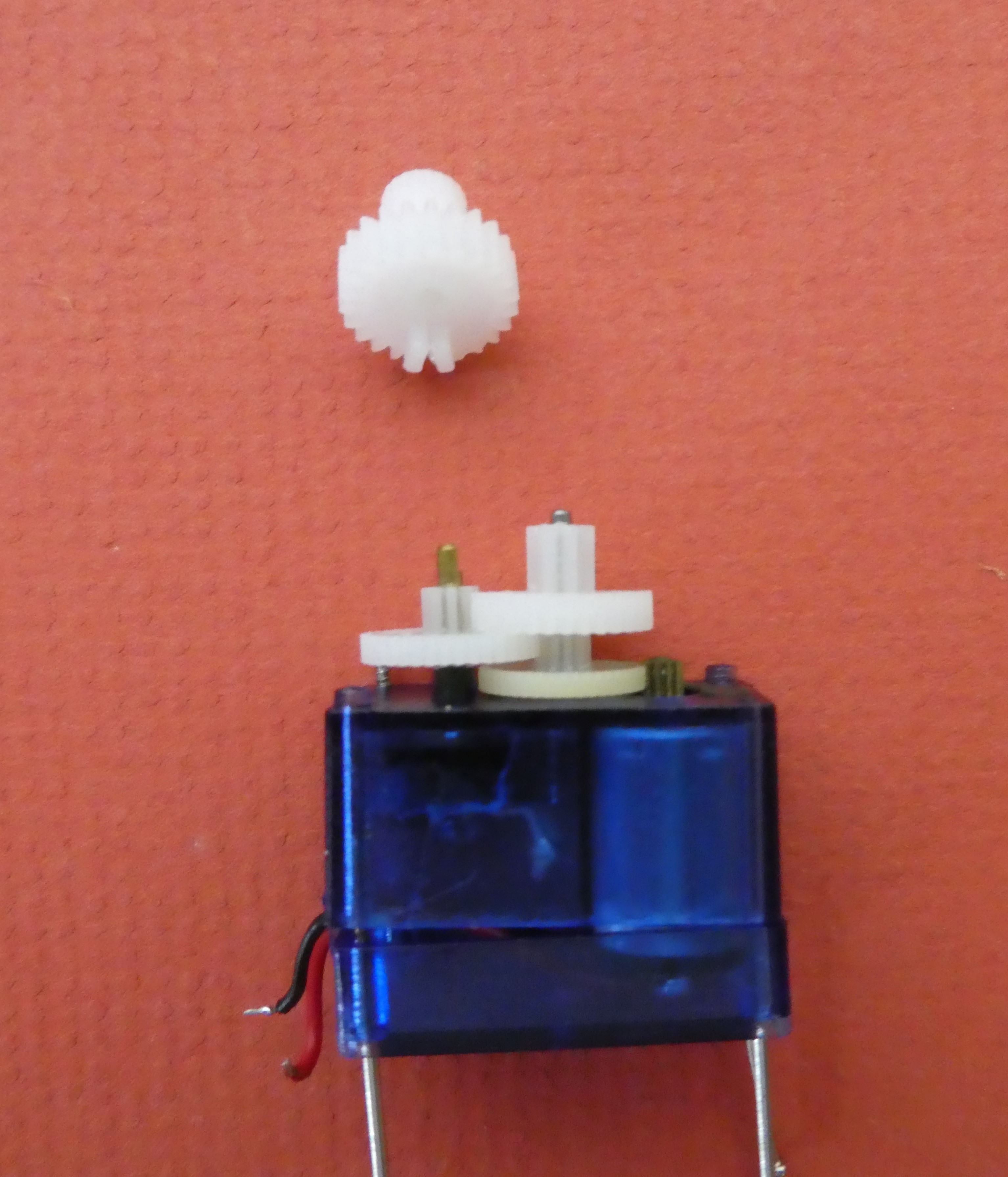 Gently slide the gear off the shaft.
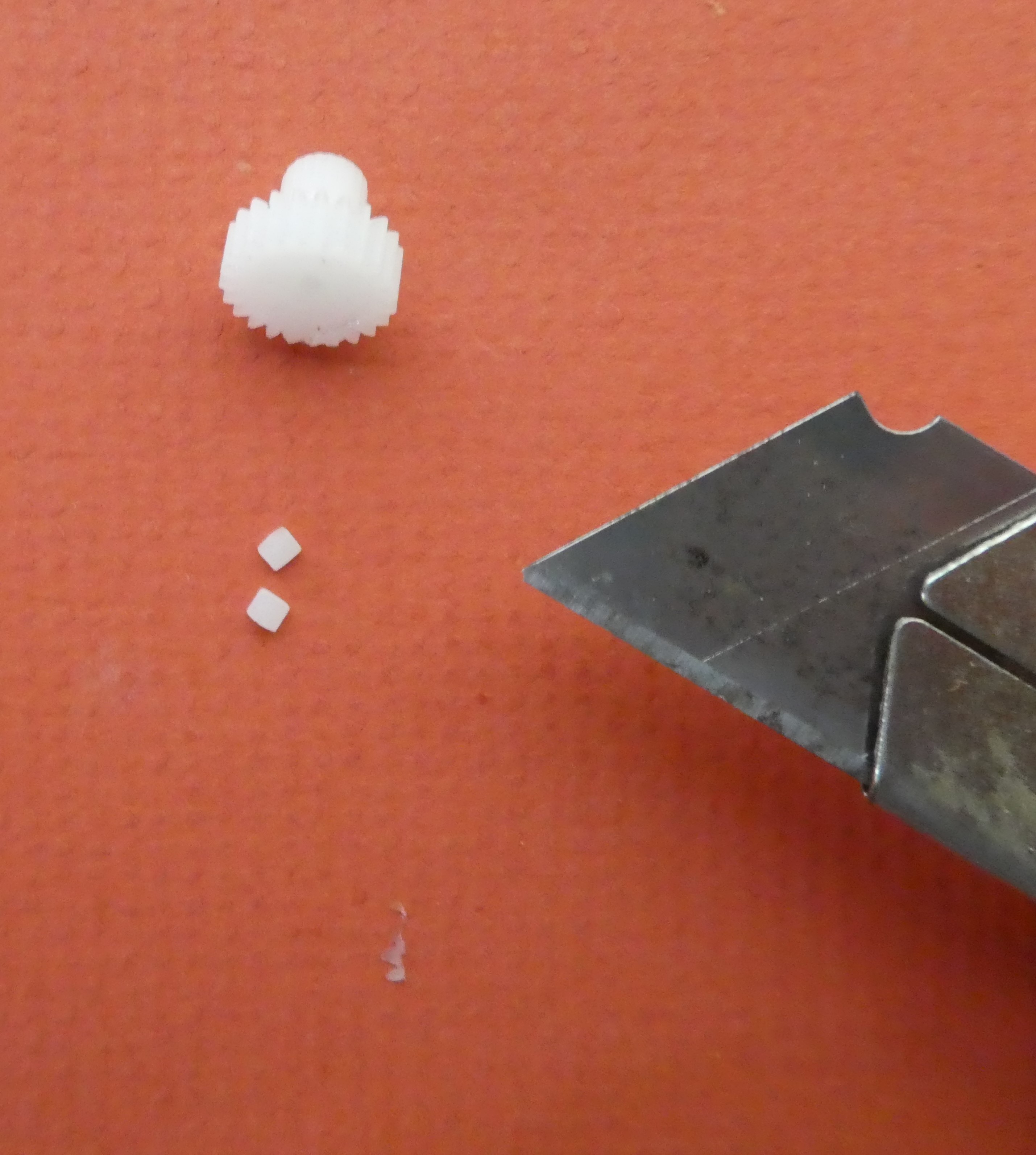 And shave off the stop with a boxcutter.
Slide the gear back onto its shaft (making sure it meshes with the other gears), and replace the top of the case.
Sub-Step 1-3: Attach a USB connector, and a switch
Because the servo operates with a low voltage and current, you only need thin wire to carry the power. The wires inside a standard USB cable are sufficient. You can repurpose a USB cable from some eWaste (mice or keyboards are a good source), but check that the cable still works with a multimeter testing for continuity between the terminals inside the USB plug and the ends of the wires (you only need to worry about the power wires). If you want to make you own USB connector, then any sheathed cable with a couple of fine conductors will do - this example used some wire salvaged from an old computer speaker. You will also need to purchase and solder on a USB plug (available from electronics or hobby suppliers) if you go this way.
USB cables usually contain 3 or 4 wires, with red and black for power and other colours for data. Sometimes there will be some shielding (usually a surrounding web of fine copper wires, but sometimes something like alfoil), and this can be cut away. You just need to make sure you have the plug the right way up (like in the diagram below).
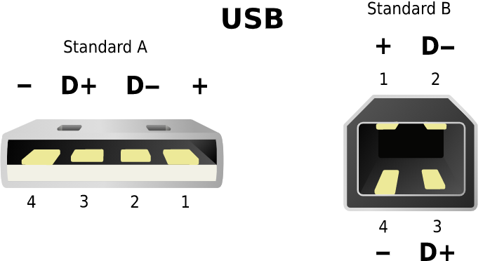 + and - are red and black respectively
By Simon Eugster – Simon / ?! 19:02, 7 January 2008 (UTC) - Own painting/graphic, CC BY-SA 3.0,
https://commons.wikimedia.org/w/index.php?curid=3353998
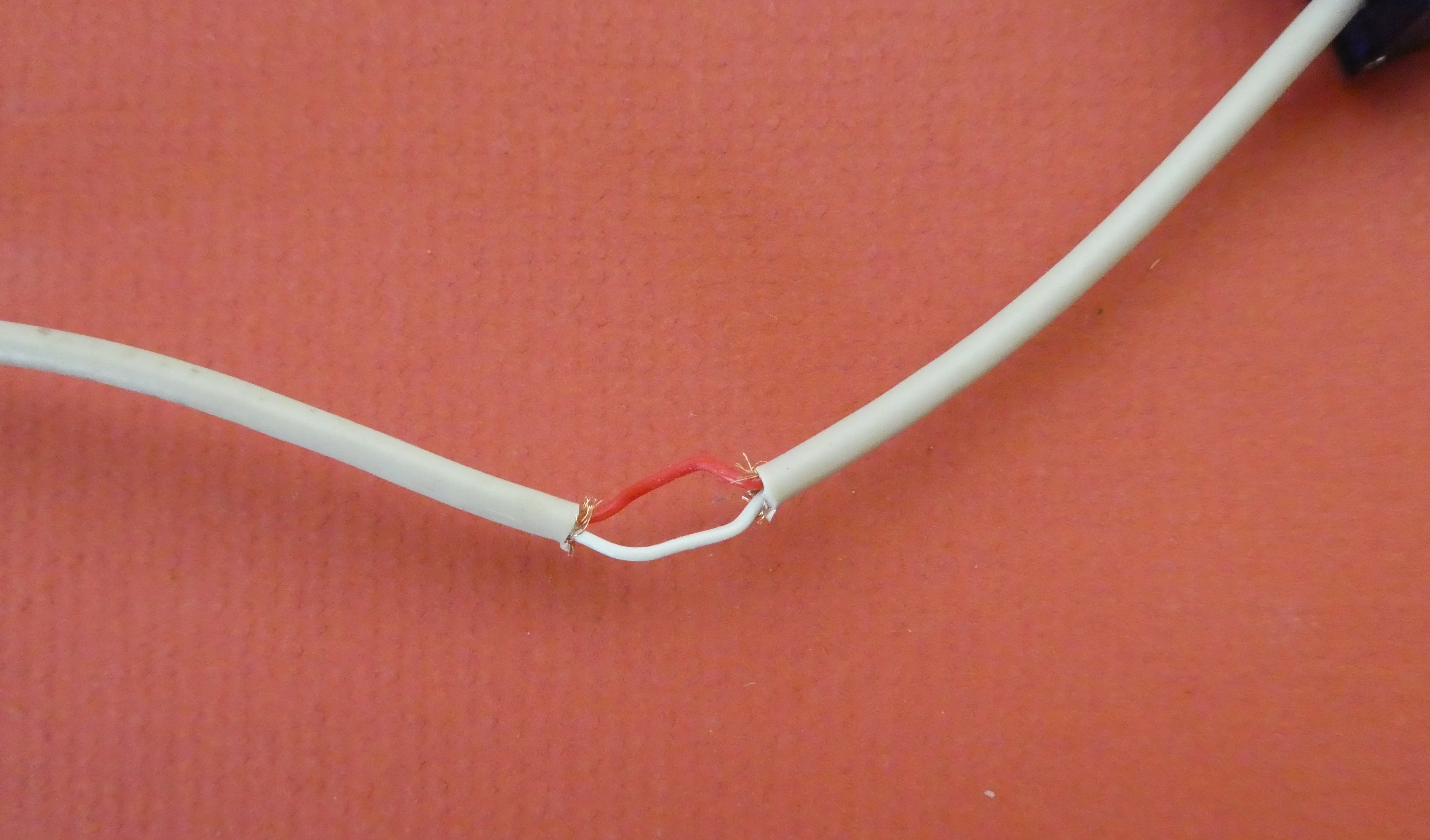 About 5cm from the end of the cable you will attach to the servo, cut away about 2cm of sheath from around the wires inside. This is where you might need to get rid of some shielding (you can see the ends in the picture, poking out from the white sheathing). Look for a red wire, and cut it in the middle. Tin the cut ends of this wire.
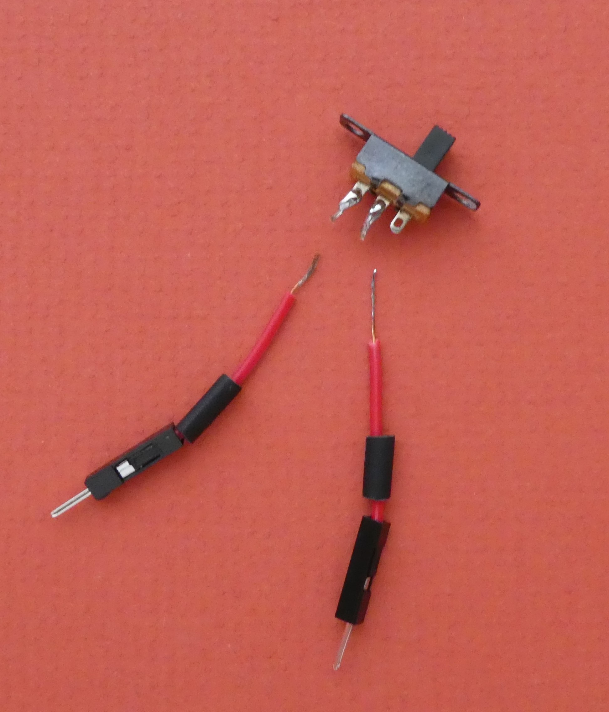
Cut your jumper wires in half, bare the ends and tin them with solder.
Attach half a jumper cable to one side of the cut red wire, and another half to the other. It does not really matter if you add both males to the cable wire, as long as two females are later attached to the switch - but you can't use all male (or all female) throughout or the necessary connection cannot be made. Adding shrink wrap insulation will help prevent short circuits later.
Do the same with the terminals of your switch - solder half a jumper to the central terminal, and half to one of the outer terminals. The switch will be on when the slider is moved towards the terminal with the wire attached, and this might influence the orientation of the switch later when it is screwed into place.
 Solder the red and black wires at the cut end of the cable onto the motor in the servo, and re-insert the screws to lock it all together. You will find a shallow cut out in the bottom of the servo case that will take the wires.
Plug the USB into an outlet, and see if the switch works. If not, check that your connections are secure, and fix them if necessary.
Step 2: Assemble the Gearbox
Standard micro-servos have an uncontrolled rotation speed of about 80rpm, and this is too fast for survival in a snow storm. The bespoke gearbox will use a gear train to reduce this rotation to about 10rpm, and also allow the attachment of shafts and platters to carry the decorative elements.
The gear train uses a couple of laser cut acrylic gears, and one that has been 3D printed. 3D printing is one way to get a single gear with both small and large numbers of teeth (and can be built from the files derived from gear generator software, imported into Tinkercad). If you want to change the speed of rotation, then gears with different numbers of teeth could be used, or added, but the size of the gearbox might make fitting them together a challenge. New gears would also need to have the same modulus (or circular pitch) and pressure angle - a rabbit hole well worth exploring.
Think about repair and disassembly before you glue the parts of the gearbox together - this is why stickytape and bolts are used here in some places. If you do use glue, then hot glue will not give a permanent bond, and can be released using isopropyl alcohol.
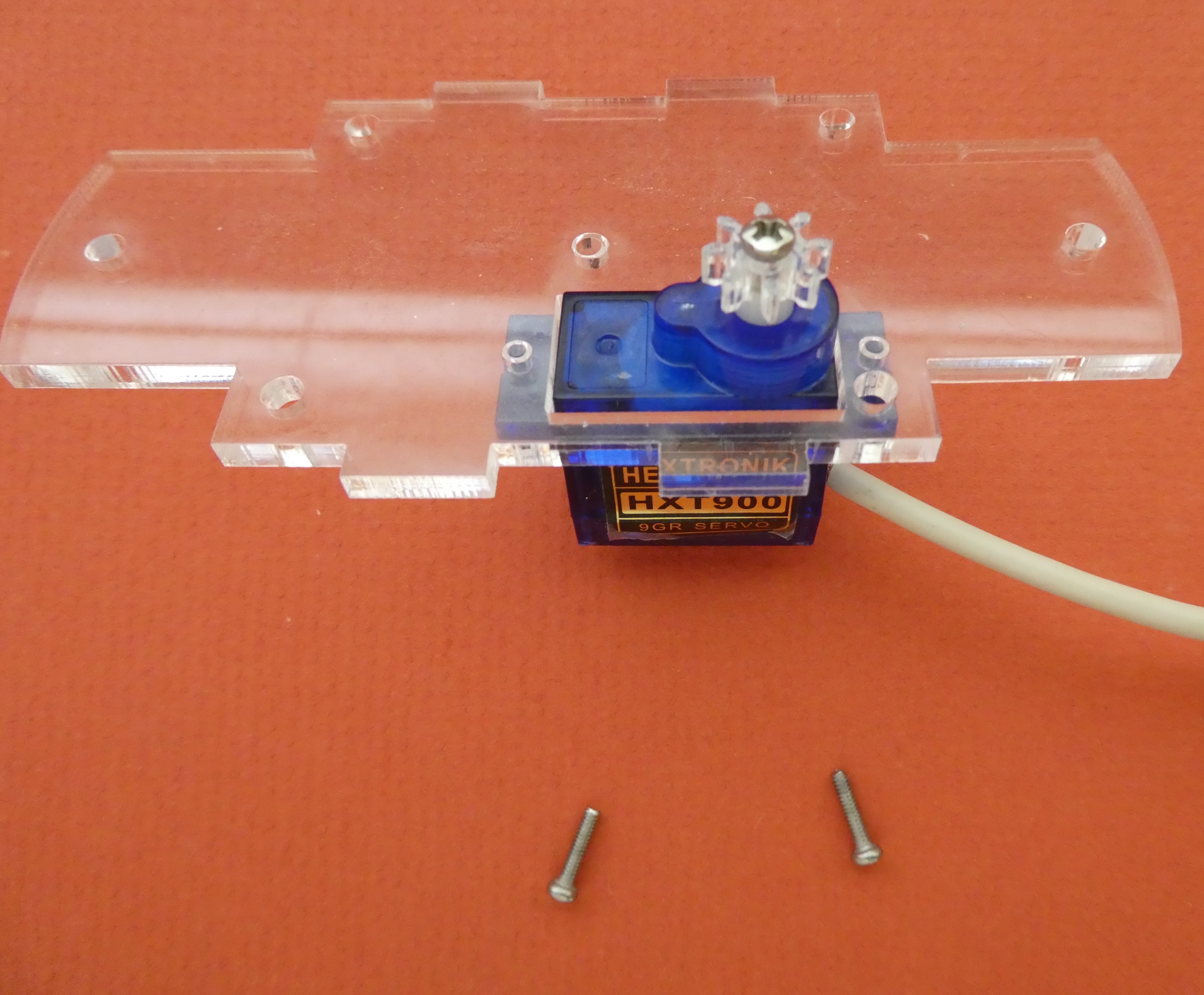
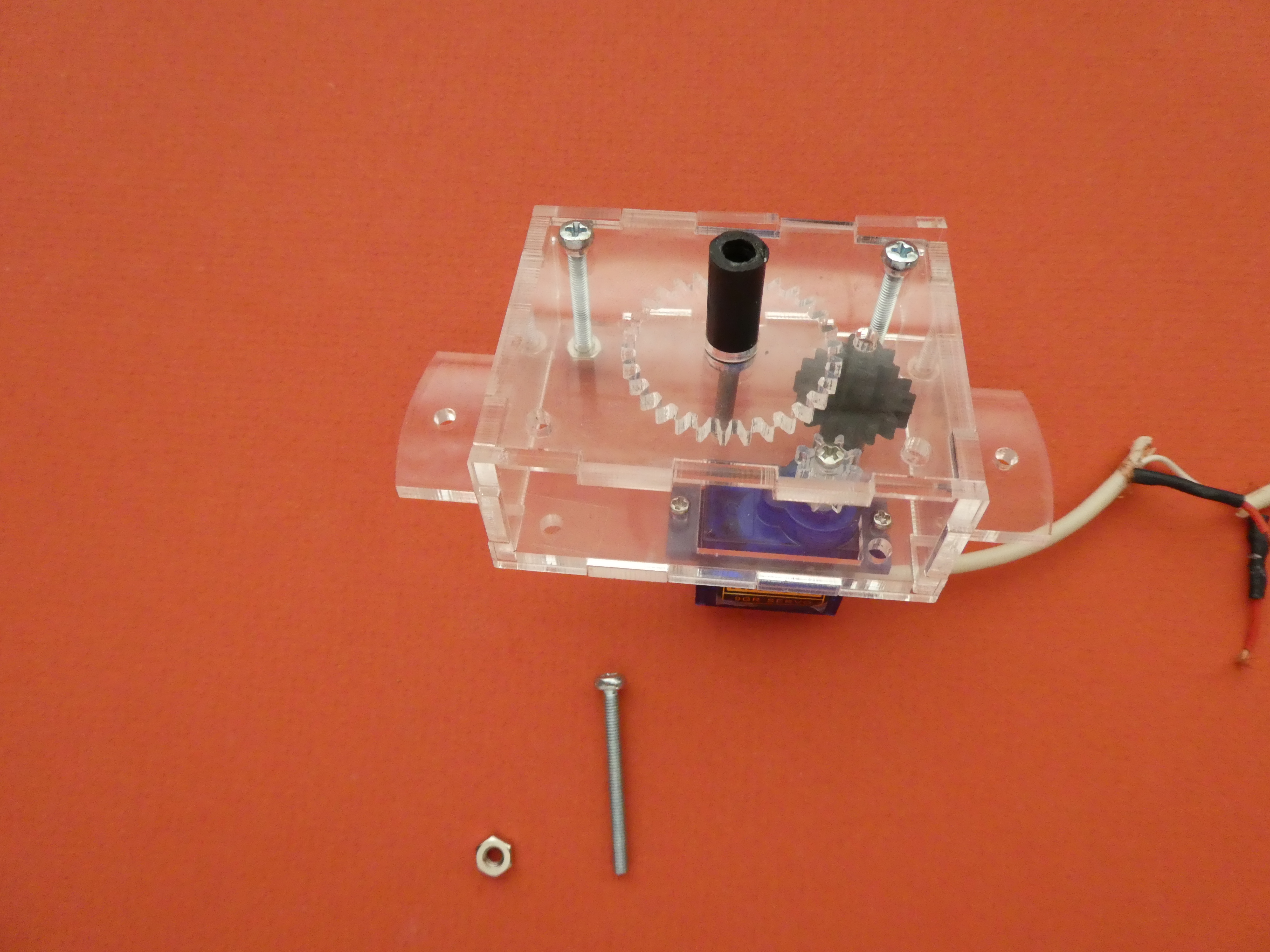
Sub-Step 2-1: Attach the servo
The base of the gearbox has a rectangular hole for the servo, and extended curved parts on either side (which are used later for positioning in the stand). The pictures will show the right way up.
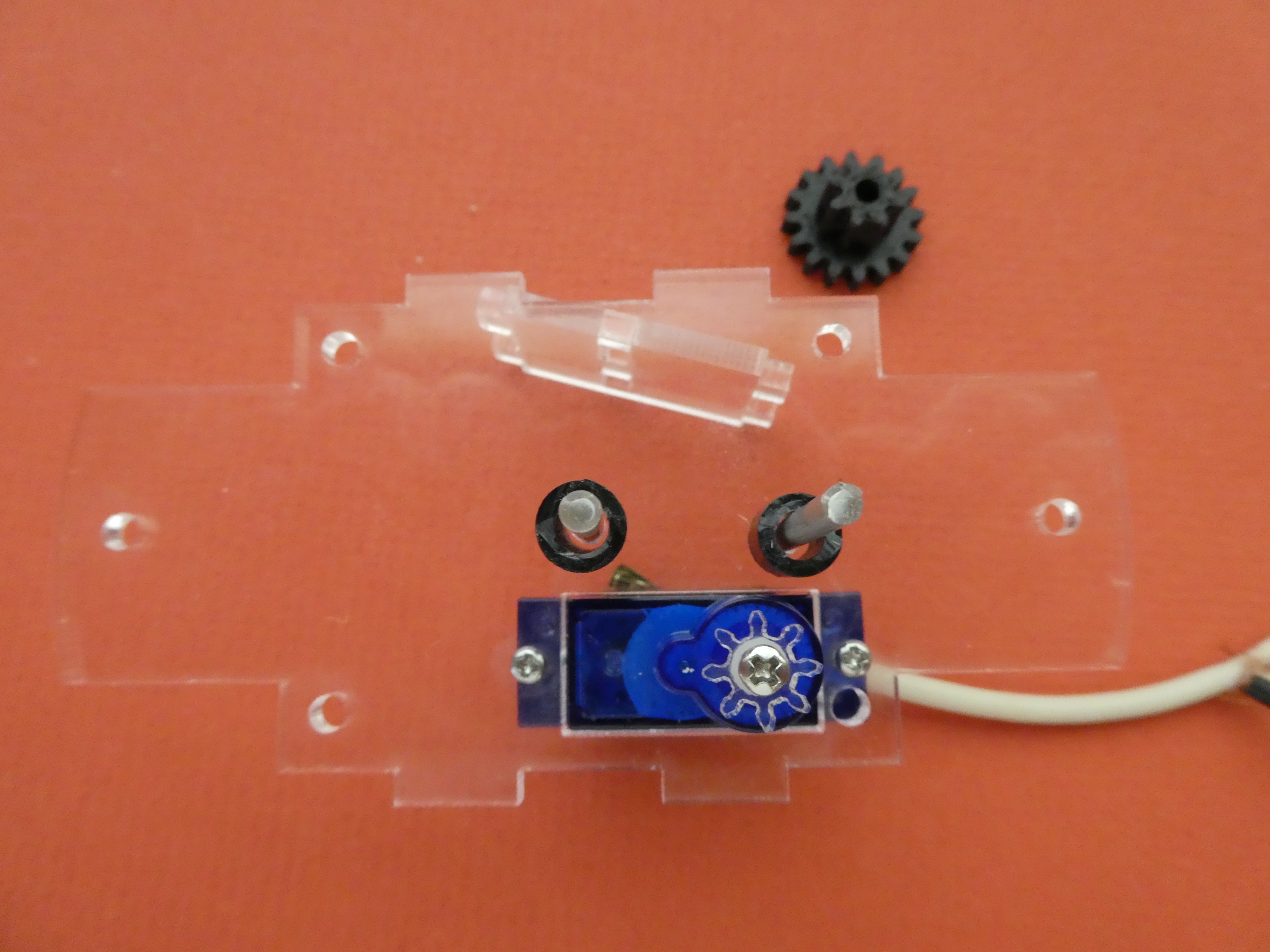
First, locate the drive cog (the smallest acrylic gear), and one M2 x 6 screw which will hold it in place. The cog has a 2mm hole, and screwing it tightly onto the white top of the servo will hold it in place.
![]()
Now push the servo into the hole provided, with the cog to the right as shown. Fix in place with the two M2.5 x 10 screws. The screws will usually bite into the servo case and hold, but nuts may be added if extra firmness is required (or only one screw aligns with the hole in the acrylic).
Note the arrangement of the two small holes in the middle of the base - the outer one goes to the same side as the cog (see the arrow).
Sub-Step 2-2: Cut the shafts and supports
This step uses boiling water in close proximity to human fingers - TAKE CARE to avoid scalding.
The shafts which run through the middle of the gears are made from 2.85mm 3D printer filament, and press fit into holes provided. To make the filament into a straight shaft, instead of the gently curved arc which is its natural state, simply cut a 10cm length of filament, and suspend it in a container of hot water (just off the boil is good). As you hold the curved filament in the water, it will heat, and soften. You will see the filament 'relax' and straighten when it gets to temperature, when you can lift it out vertically, and apply gentle pressure between fingers holding it at both ends to force it straight. In a few seconds it will cool, and harden again. If the ends are still a bit curved (where you kept your fingers out of the boiling water), they can be cut off. Don't pull too hard, or the filament will stretch, and get thinner.
The supports which hold the gears at the right level in the gearbox are cut from rigid polypropylene irrigation risers, which have a 4mm hole down the centre. The tricky part is to get ends which are as perpendicular as possible. Once cut to length, some fine shaving with the boxcutter can square the ends.
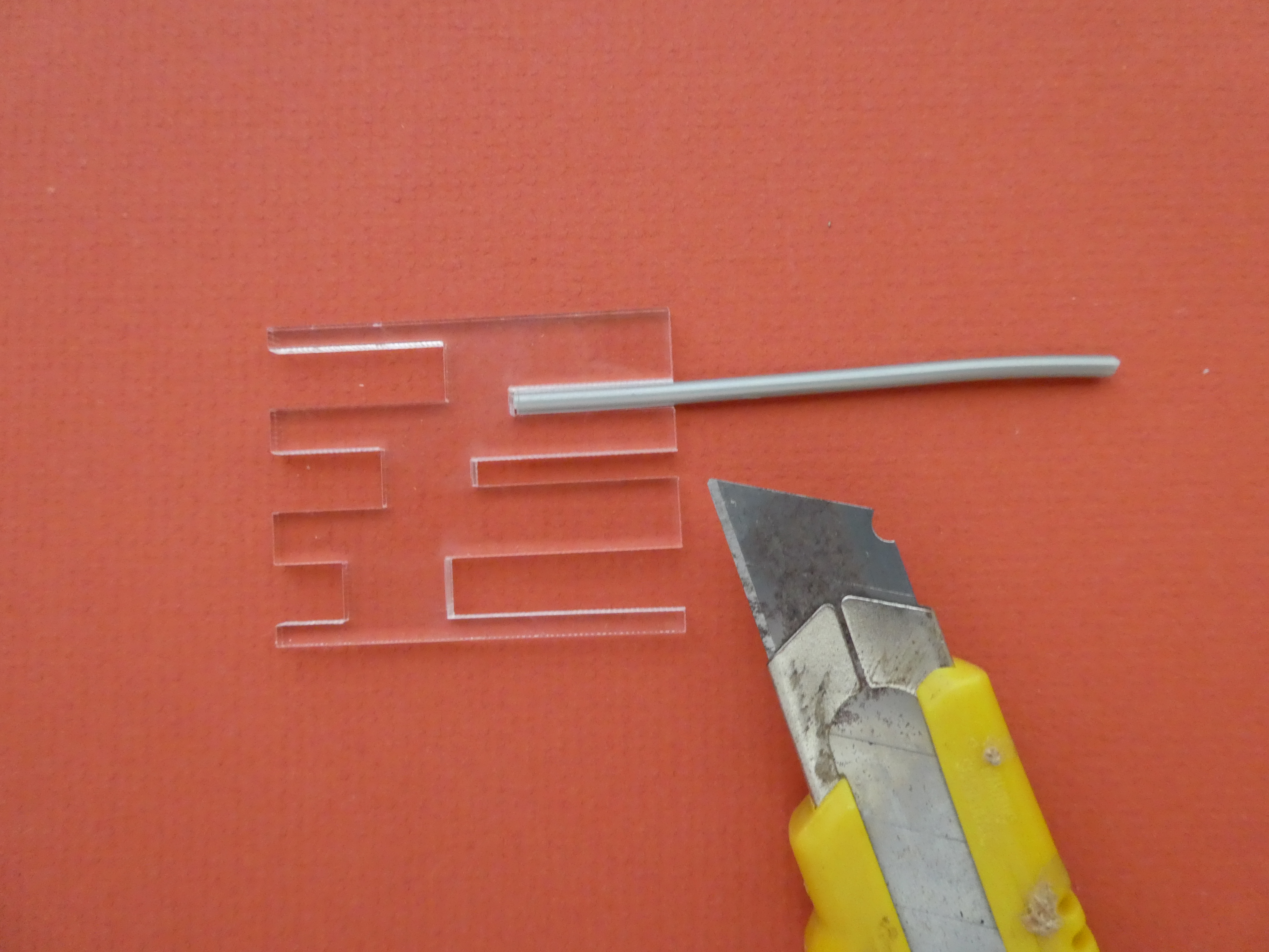
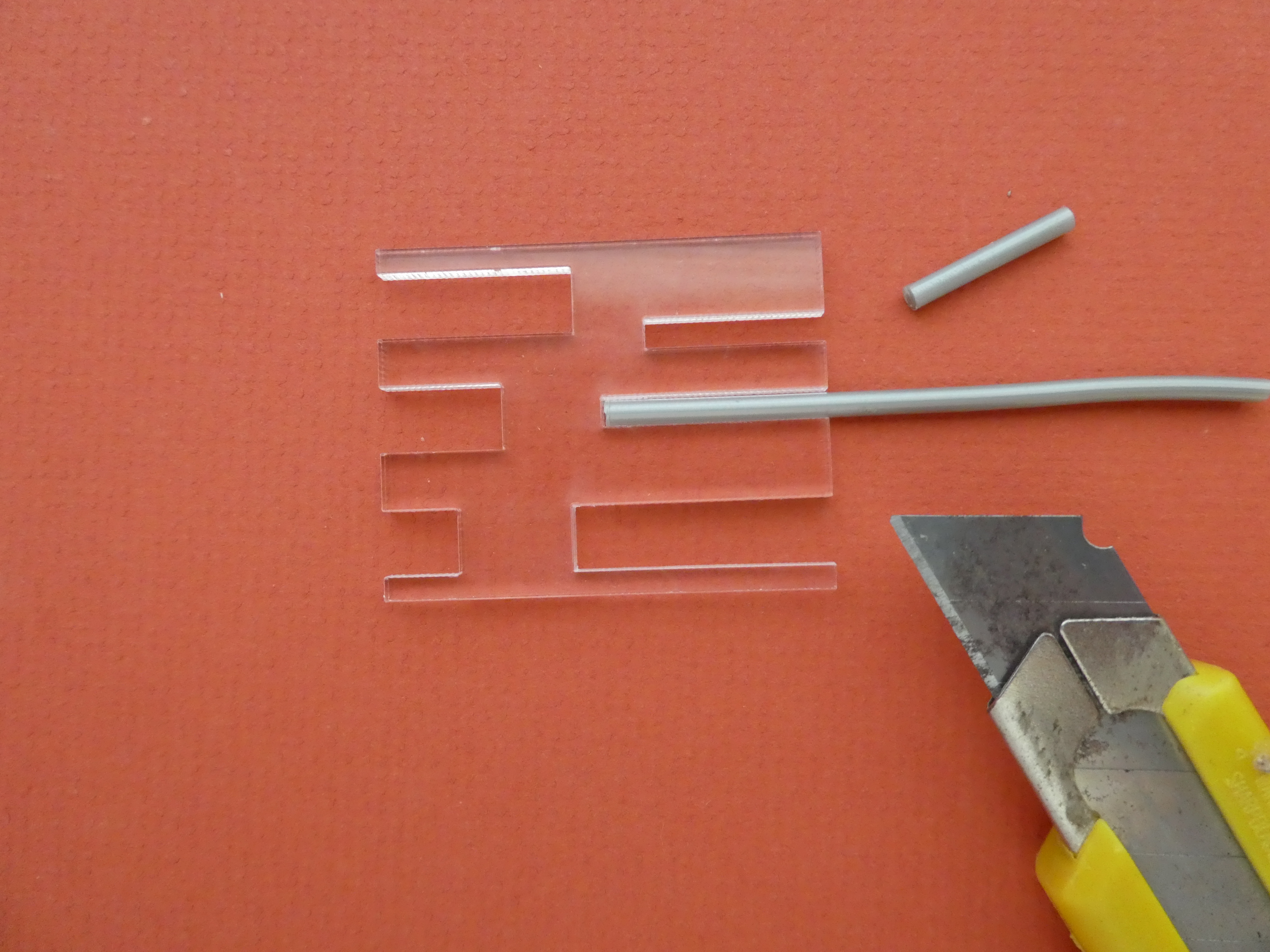
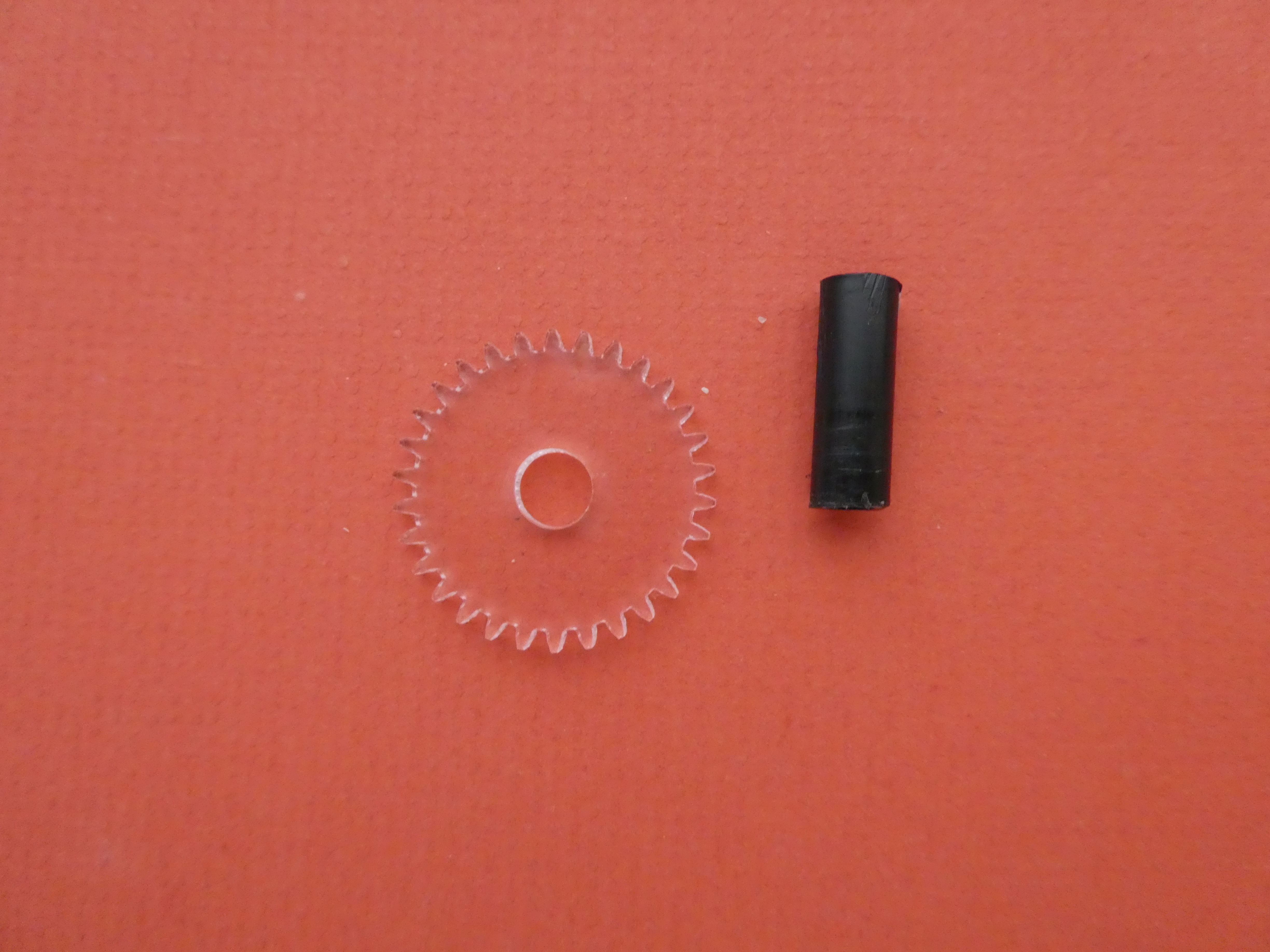
Slide the shaft material into the template provided, and cut to length with a boxcutter. The 3D printer filament is quite hard, but you can score around the outside by rotating the filament in the template, and snapping off the piece. Be sure to align the blade of the cutter with the outside of the template accurately to get the right length.
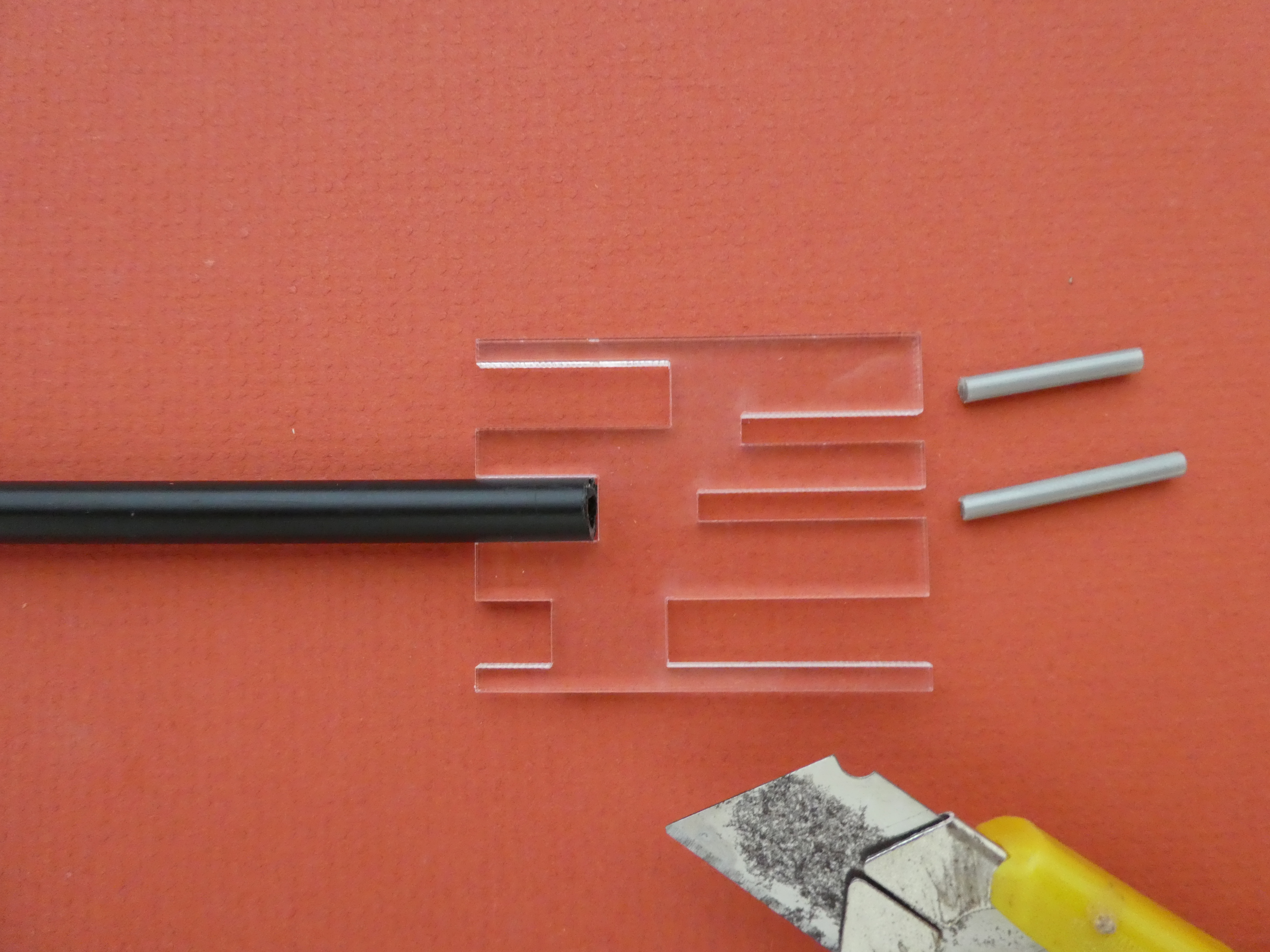
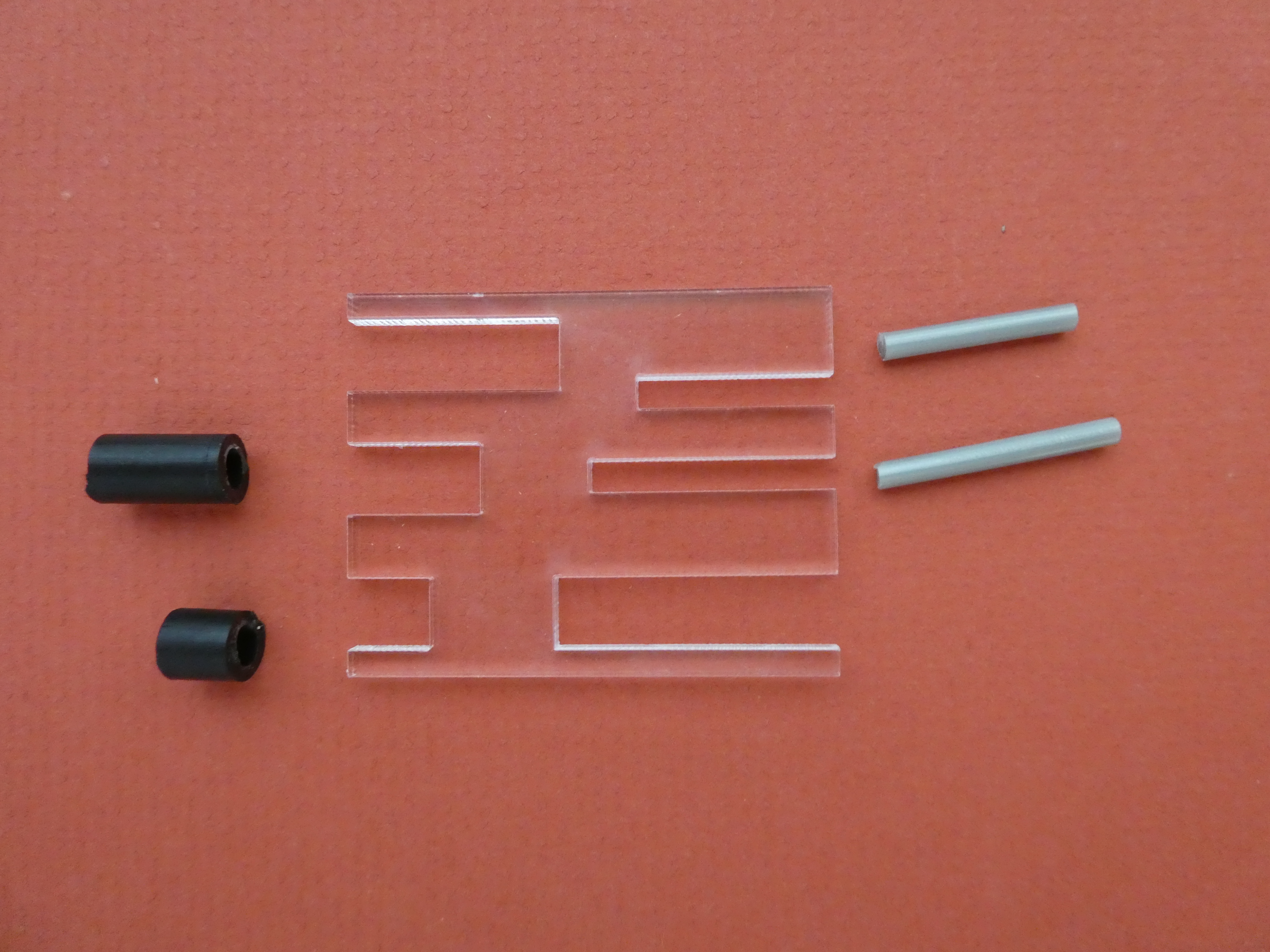
Do the same with the black support tubing, using the wider holes in the template. Again, this material is quite hard, and rotating the tube combined with persistence and a fair bit of force will be required. The longest two support holes produce pieces for use with the magnetic drive described later.
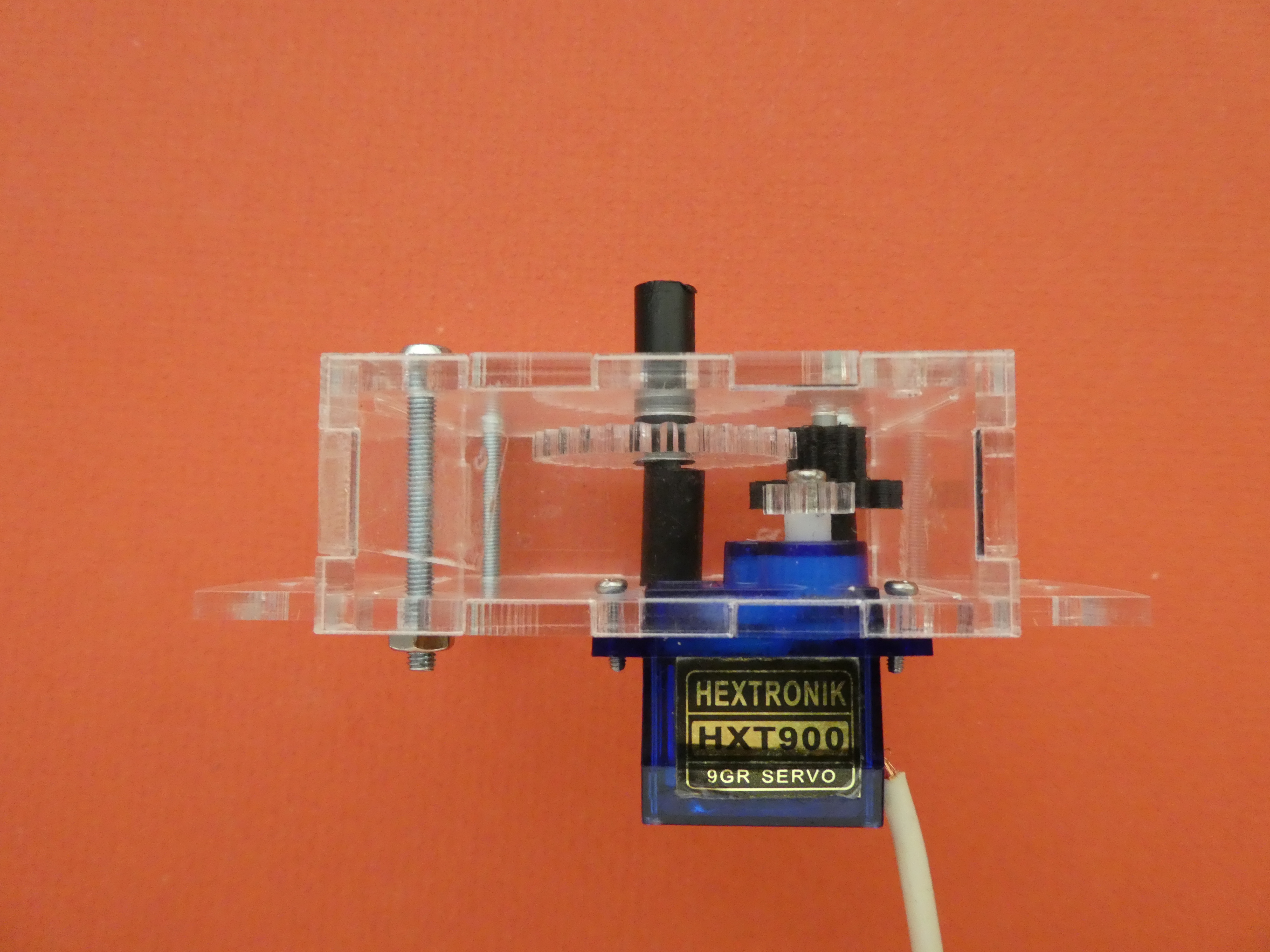
Sub-Step 2-3: Assemble the gear train
The gear train needs to be built inside the gearbox before it is closed. It is important to make sure the shafts are located in holes provided in the top and the bottom plates to keep them vertical.
The two shafts press fit into holes in the base of the gearbox as shown. The shorter shaft goes in the centre hole.

Slide the black supports over the shafts, with the longer one in the centre as shown.
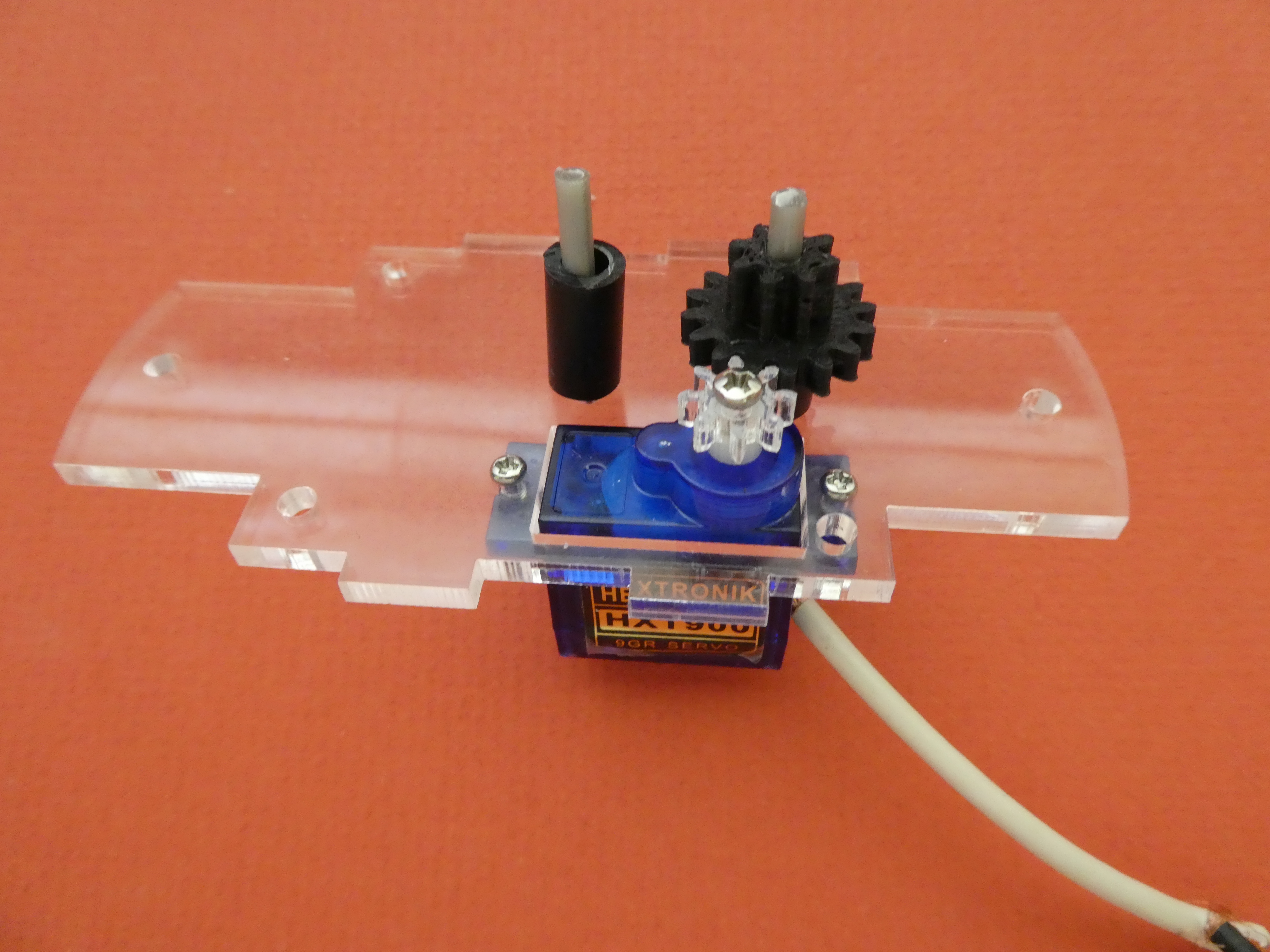
Locate the 3D printed gear, and slide it onto the long shaft (the one on the outside), with the wider gear to the bottom. Make sure it meshes with the cog.
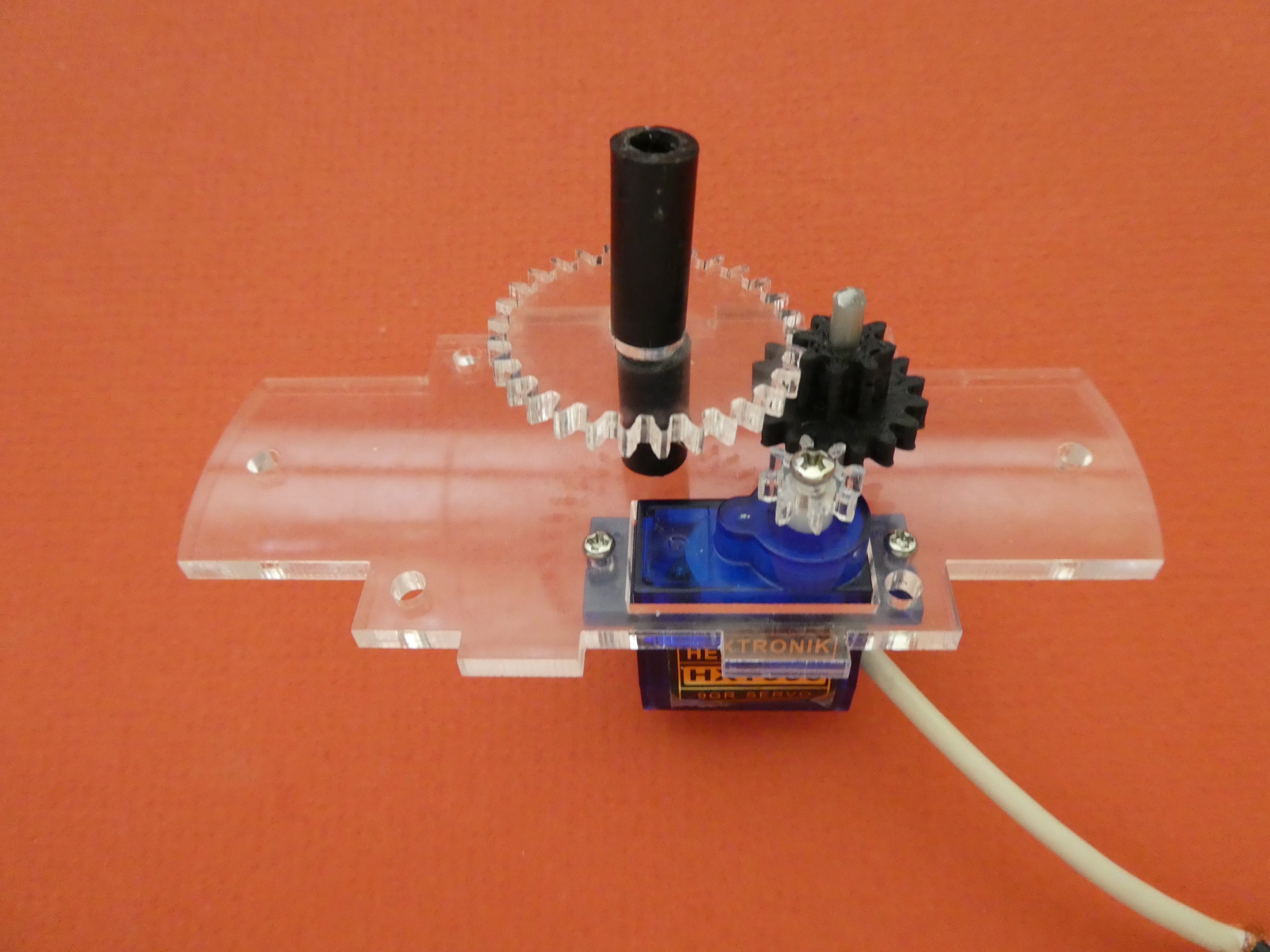
The larger acrylic gear has a hole in the centre to take a longer piece of support tubing. The size of this piece will depend on what type of display you want, as described later. As you slide this gear onto the centre shaft, make sure it meshes with the 3D printed gear.
Sub-Step 2-4: Build the gearbox
All you need to do now is assemble the gearbox onto the base. Using stickytape to hold the sides together, rather than glue, is a good idea at this stage so minor adjustments can be made later. When you bolt the top and bottom together, the pressure will hold everything in place.
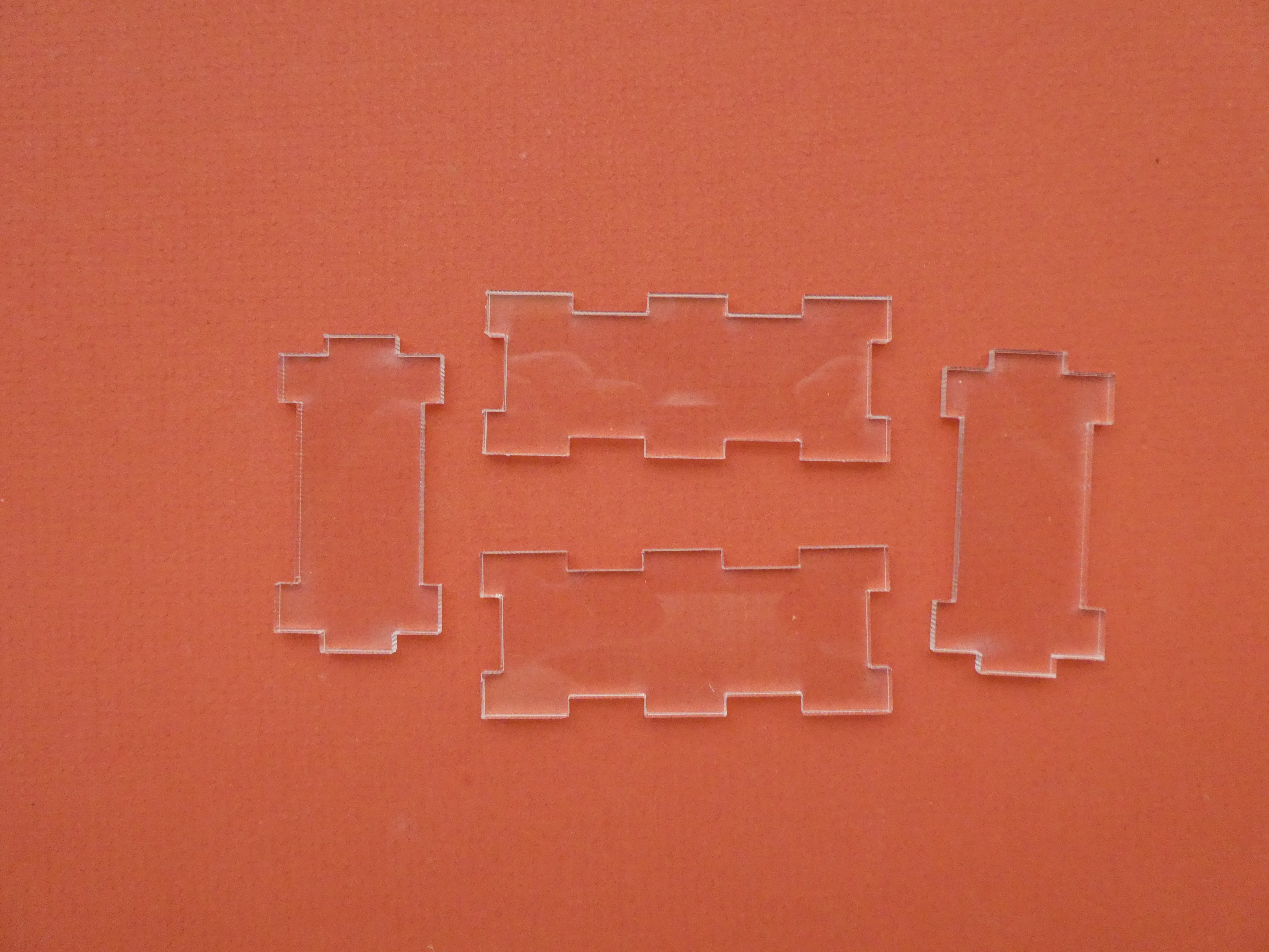
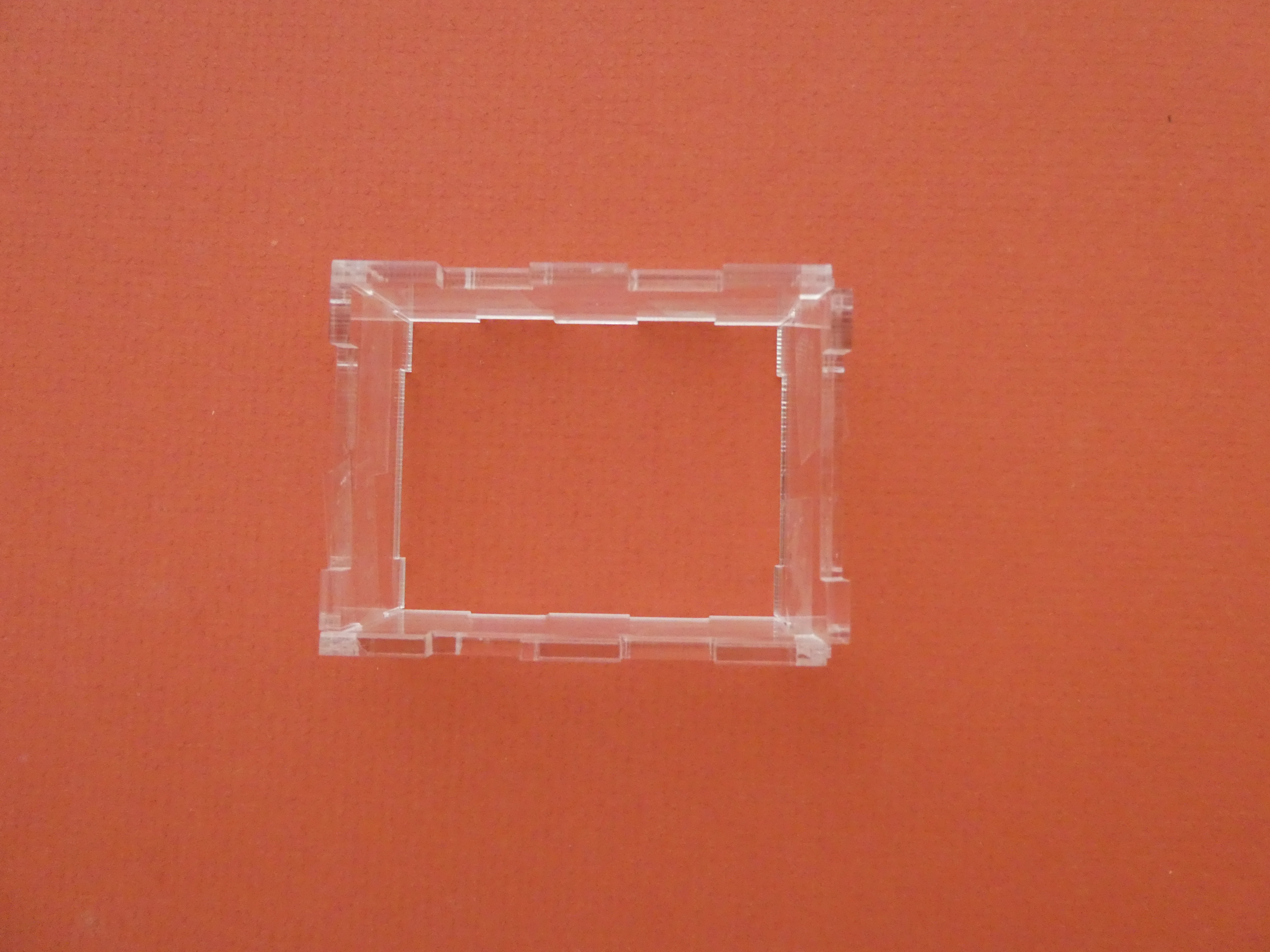
Locate the sides of the gearbox, and fit them together with tape around the corners.

Place the side assembly onto the base, and have the top ready. You have to thread the black support coming from the top of the large gear through the hole in the gearbox top as you slide on the top.
At this stage, it is useful to pull one side out of the gearbox, so you can push the shafts around a bit to align them with the holes in the top before pressing everything together. Just remember to put it back in place before tightening the nuts on the screws.
The hole for the side shaft ( the one with the 3D printed gear) is not in the centre of the top or bottom, so if it can't be made to fit easily, try flipping the top over. Check it is vertical by looking from the side. You might need to push it up from the bottom to get it to engage with the hole in the top surface, too.
You can now add the M3 x 30 machine screws to the corner holes, and tighten them up with the M3 nuts. One corner hole is too close to the servo for a screw to fit, but this does not affect the integrity.
Do a final check that all the gears mesh, and everything is vertical.
Step 3: Assemble the Carousel
The carousel is whatever you expect to see inside the dome when you are finished. There are a few different ways of making this bit, and some alternatives are explained below, with the simplest first. You can mix and match a bit, too, adding an extra support to reduce wobble, even for the simplest version.
If you intend to fill the dome with liquid (realise it will be heavy, and leaks are possible), then the magnetic coupling will be used. A magnetic coupling avoids having any shaft going through the bottom of the dome base, and so makes leaks less likely.
Version 3-1: A simple spinning platter
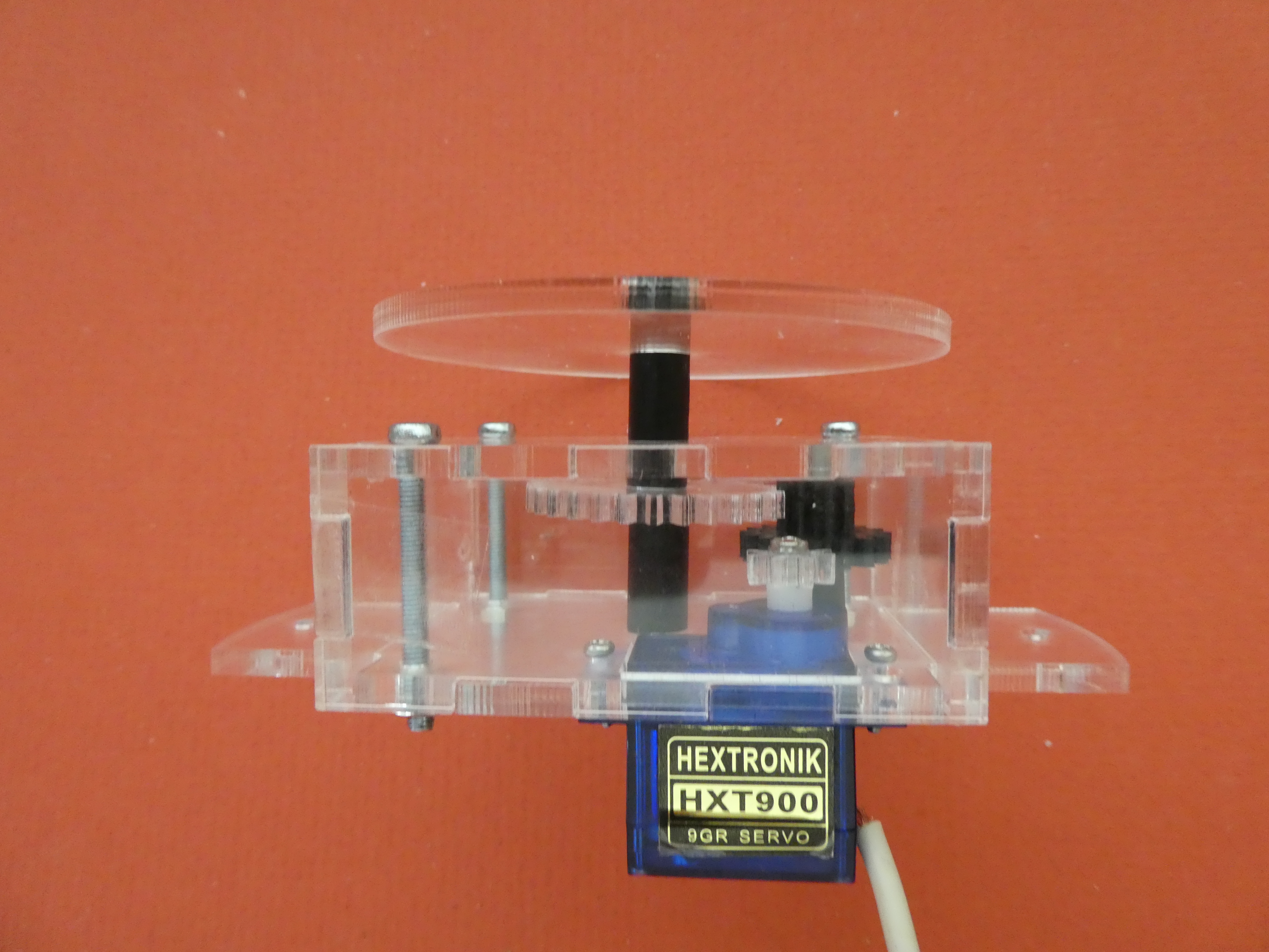
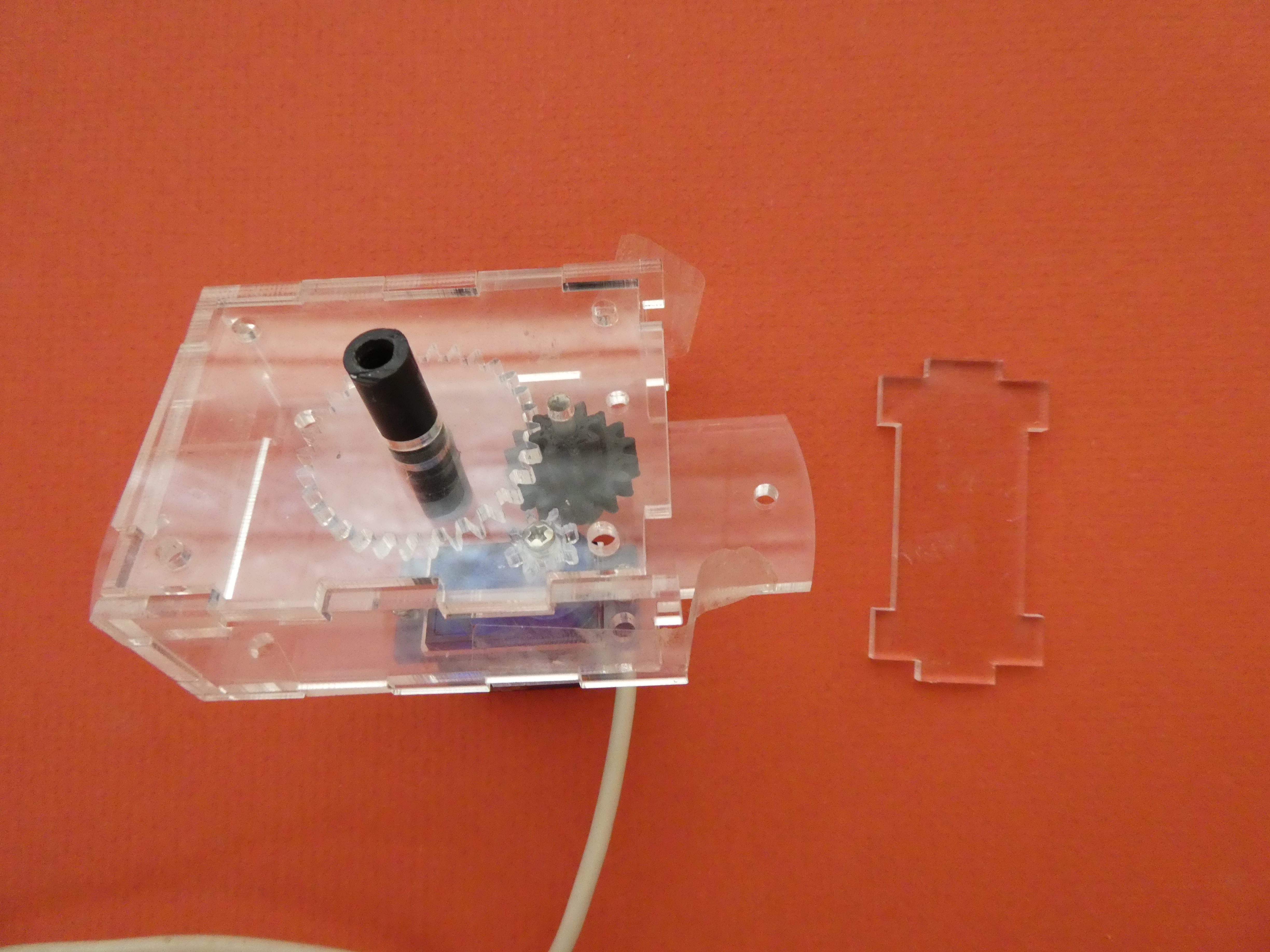
Your laser cut parts includes a platter - the smaller round piece with a single hole in the centre. This will press fit (gently) onto the other end of the black support coming through the top of the gearbox - meaning that as the shaft rotates, so will the platter. You could have the platter at the same level as the base of the dome, or a little above or below, depending on how long you cut the support. Trial and error will be required.
Keeping the support short (as in the picture) will minimise wobble.
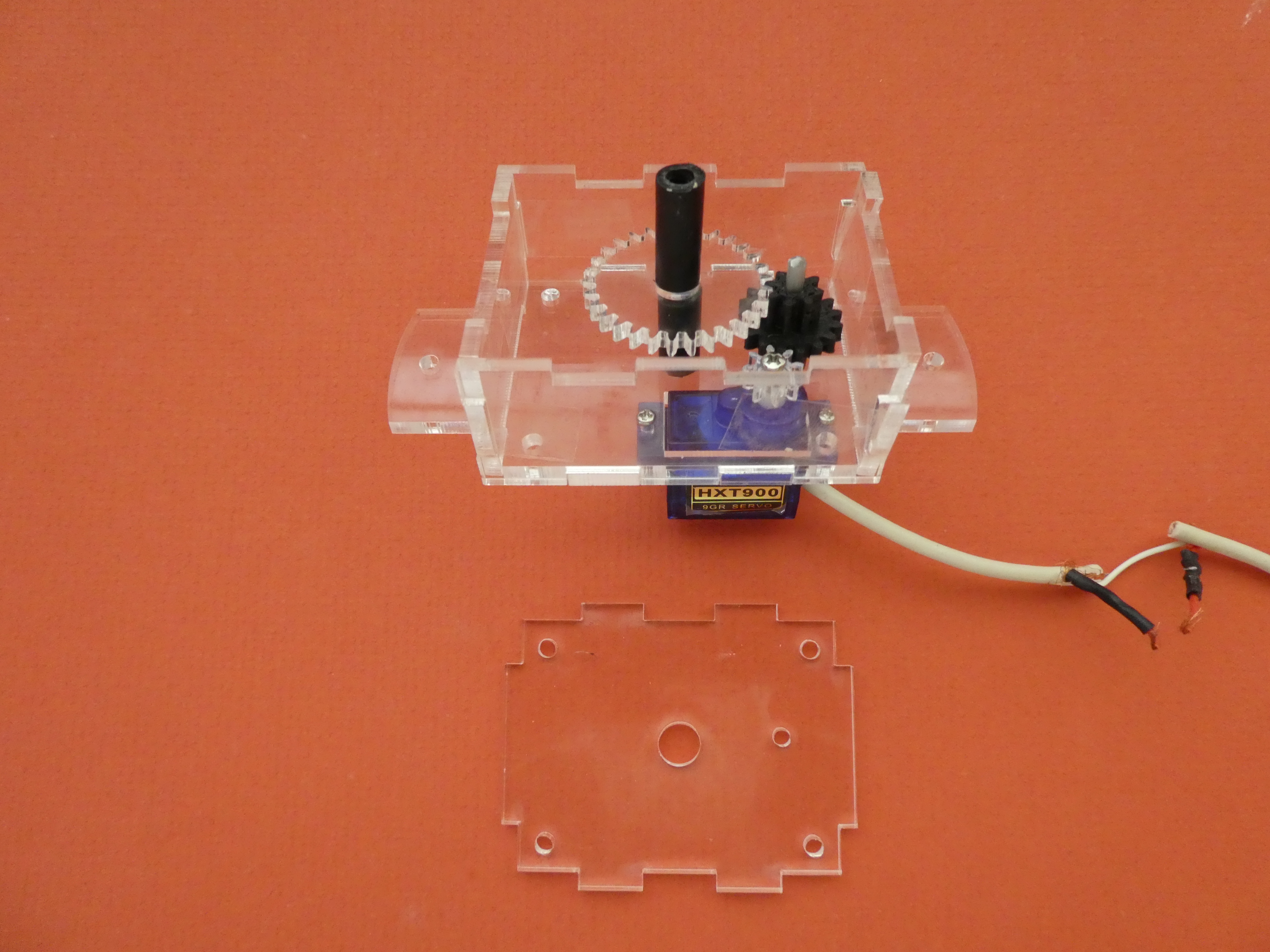
The bottom plate used for the spinning platter has a central hole to allow the shaft from the gearbox to pass into the dome:

Version 3-2: A simple rotating tall shaft
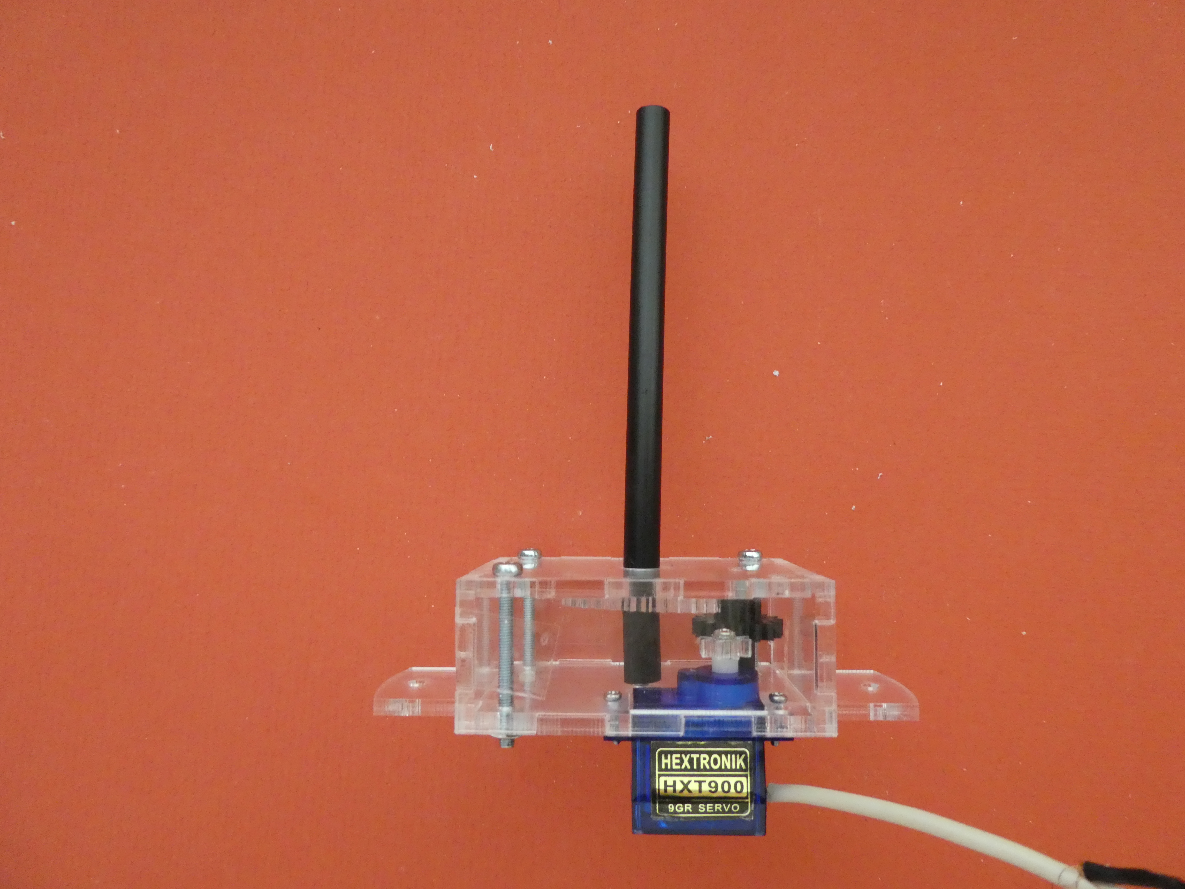
Like the platter, this version is simple, but will be prone to wobble as it gets taller. This is a good basis for building a tree, an umbrella or a merry-go-round, but you will need to figure how to hang things off the tall shaft.
This version uses the same bottom plate with a central hole as shown above.
Version 3-3: Magnetic Coupling


Two 32 mm ferrite magnets are fixed to the underside of the 1.5mm thick support as shown (hot glue should work, but keep the glue thickness to a minimum). The magnetic coupling is mounted on a short shaft using a 4mm self-tapping pan-head screw inserted through the central hole in the support, and screwed into the hollow shaft. Make sure the the top of the screw head is higher than the magnets to avoid excessive friction when the shaft is rotating (the screw head will contact the underside of the dome bottom plate when assembled).
The assembly shown (with the magnets UNDER the support) was used because the magnets were too thick, and projected above the screw head . If you have weaker magnets or heftier screws, flip the assembly over, and screw into the shaft with the magnets uppermost - this reduces the distance to the other half of the coupling, and so increases the magnetic force applied.
The bottom plate for the dome used with the magnetic coupling does not have a central hole:

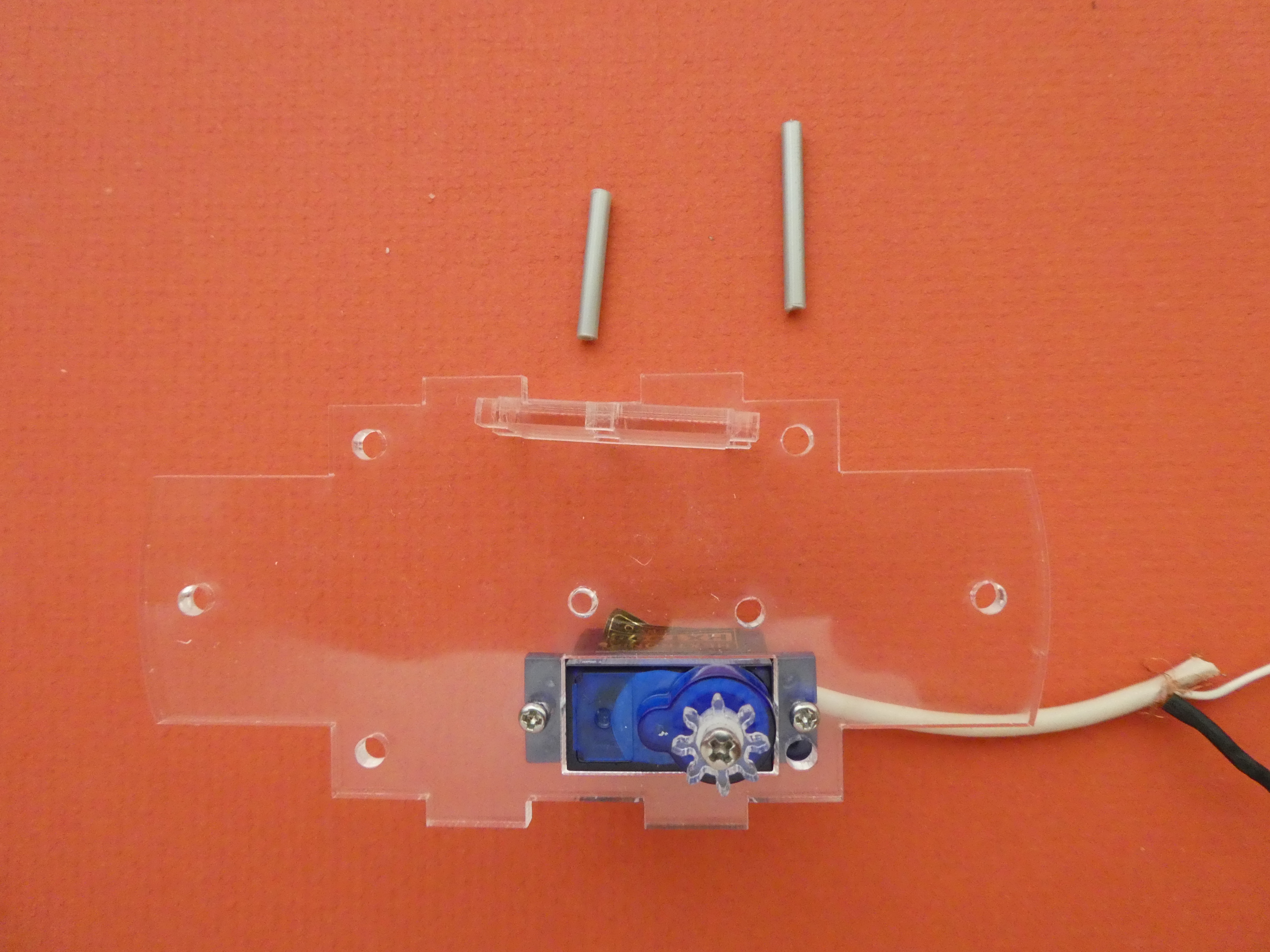
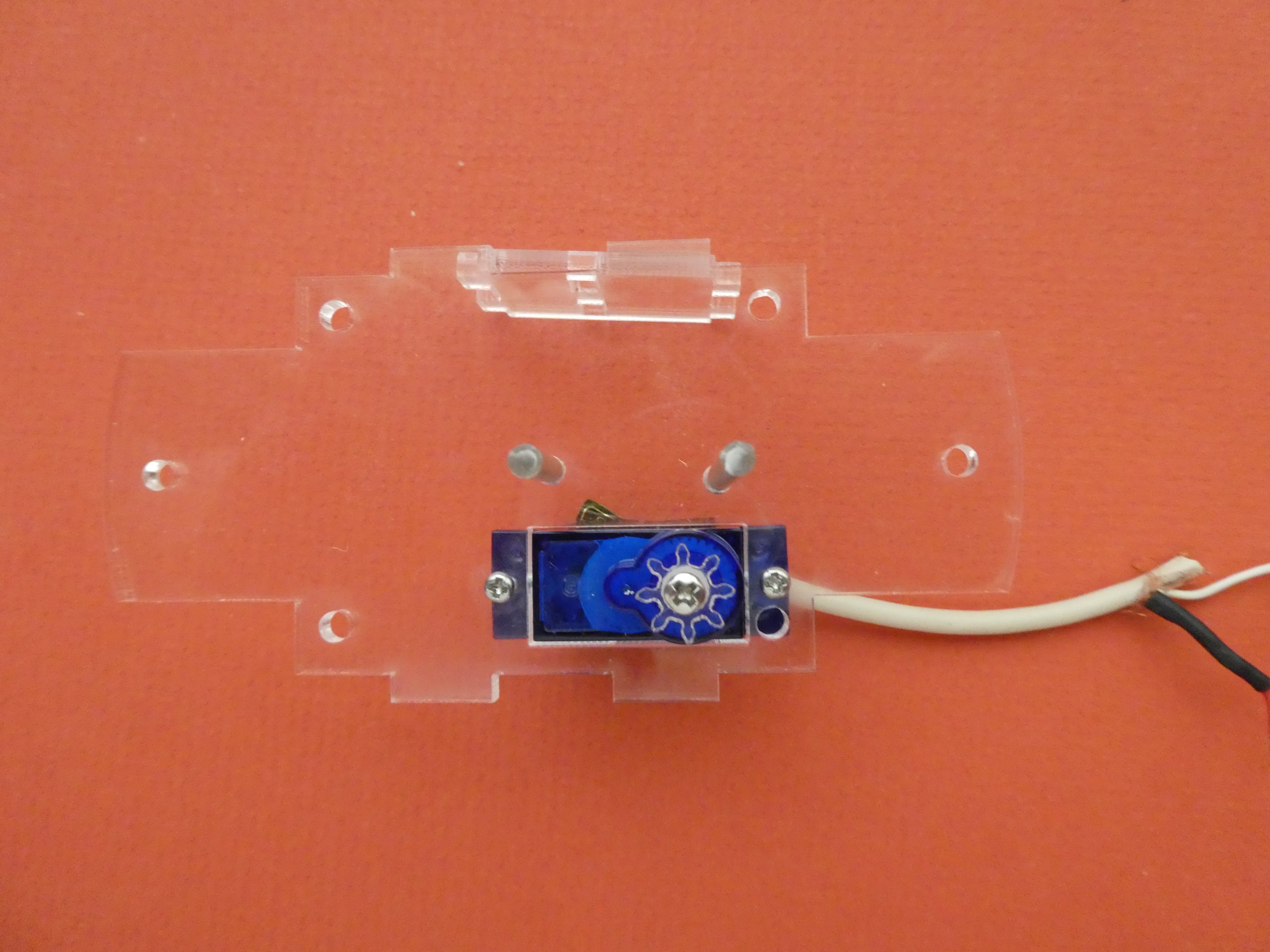
Sub-step 3-1: Assemble the shaft support
The shaft support is mounted above the dome bottom plate, and will help to stabilize a tall (or wobbly) shaft. This structure is also essential for the magnetic coupling version, since it holds the other half of the coupling in place.


The vertical supports have holes to take the spreader but these holes are not centrally located. You might need to flip them around to make them fit. CHECK THAT THE SPREADER IS HORIZONTAL BEFORE GLUING!
Now add the upper plate, and your support is ready for installation:

The upper plate shown is made to take the platter, but the plate shown in Version 3-1 above could be used for a tall shaft.
Sub-step 3-2: Assemble the magnetic coupling support
If you are using the magnetic coupling, then the top half will be inside this support.

Two steel washers 25mm in diameter are glued to the other 1.5mm thick support, and fixed to a shaft with a 4mm screw as for the magnets. The screw head faces downwards, and sits on the surface of the dome bottom plate.
Minimising the distance between the magnets and the washers that follow them will improve the strength of the coupling. This is why the thinner 1.5mm acrylic is used for the supports, and the washers are mounted under the support, while the magnets are mounted above. You could try using magnets in place of the washers, but the attractive force may overpower the servo.
Step 4: Installing the Switch
The base for your globe is cut from 110mm PVC pipe. The height of the base will depend on your aesthetic judgement about how much of the workings you want to be visible - a taller base allows you to set the gearbox and supports lower.
For a minimal set-up, using a simple platter and no shaft support, about 90mm is enough. A magnetic coupling and shaft support might need a base 150mm high. The best approach is to assemble your device, and measure the height you need before cutting the PVC pipe.
Whatever the size of your base, you will need to make a hole about 1cm from the bottom to take a switch that controls power to the servo (unless you want the globe to spin continuously while ever it is plugged in to USB power.
Sub-Step 4-1: Make a Hole


Use a drill bit no larger than the width of your switch to make a hole in the PVC base.
You can add another hole directly below (if you switch is long enough), and then use a small file to shape the hole to take the switch snugly.
Sub-Step 4-2: Fit the switch


Disconnect the switch from the USB cable, and mount it into the hole from the outside.
If your switch has screw holes for fixing, mark them, drill some holes and screw the switch into place.
Add some hot glue from the inside for extra security.
Sub-Step 4-3: Make a Mouse Hole
The USB cable will need to go under the bottom of the base after assembly - making a mouse hole big enough to take the cable will allow everything to sit flat:

WHY?
Making the mouse hole close to the switch means that both can be hidden from view if desired by rotating the globe away from the viewer.,
Step 5: Final Assembly
By this time you should have a good idea about the scene the you are going to depict inside the finished globe. Your creative vision now needs to extend to the vertical location of the different elements: a rotating platter might be level with the top of the PVC base, or you might want to have a central element raised higher than the objects arranged around it, for example. Or you might want to make the magnetic coupling visible to impress your friends. Play with assembling the scene until you are satisfied (but don't glue anything down yet), and then decide where you want the floor to be - measure or mark this level on the inside of the PVC base before moving to the next step.
Sub-Step 5-1: Make a Couple of PVC Circlips


Cut a couple of 1cm wide rings from the end of the PVC pipe you used for the base, making sure to keep the ends of the cuts square so the driving shaft will be vertical. If you have access to a drop saw (and the skill to use it), this will make things easier.
To turn the ring into a circlip, cut out a 1cm segment as shown above. You can now squeeze the ring closed enough for it to slip inside the pipe, and it will spring back to make a snug fit to the interior when you let go. If the circlip does not fit, cut a bit more of a gap.
Sub-Step 5-2: Fixing the Floor

If you have already marked the floor level you want, then you just need to slide the floor inside the base, and align it to the mark.
If you need to see what you will get, put the gearbox and floor assembly inside the base as shown above, and slide it up and down until you are get the effect you want. Measure or mark where the floor will sit.
You now need to hold the floor in place inside the base upside down while you glue in the supporting circlip. If your floor is to be flush with the top of the base, then just put the base on a level surface, and push the acrylic floor to the bottom. If you want the floor a bit below the top of the base then putting something on a level surface to support the floor at the required height inside the base will help if you levitation skills are undeveloped. Cutting a few discs of cardboard and stacking them up is an easy way to do this - just try to make them big enough to support the whole floor, and prevent wobbling.
Slide a circlip inside the base until it touches the floor evenly all around, and hot glue the circlip in place.


Sub-Step 5-3: Fixing the Gearbox

Mount the gearbox inside the base using the other circlip - you might need to push the shaft through the floor, and have a look while sliding the gearbox up and down inside the base to get the right height. Mark where the bottom of the gearbox sits inside the base, and hot glue the final circlip in place (but make sure the gearbox is beneath the circlip when you glue it, as shown).
Add more hot glue to the tabs on the gearbox base to stop it sliding around on the circlip (you can flip everything right way up, remove the floor and do this from the top).
Sub-Step 5-4: Connect the Switch
Before you start decorating, connect the switch to the USB cable. Use more hot glue to hold any loose wires in place, and add a bit to the mouse hole to hold the cable in place there too.
Step 6: Decorate and Seal the Dome
Before sealing the dome in place, sort out the display elements, and glue them in place. This is a last chance to alter the height of the shaft - you can cut a new one and insert it onto the gearbox through the hole in the floor (just don't push too hard, or the gearbox might be displaced).
When you are satisfied, run a bead of hot glue around the bottom edge of the dome, and push it down onto the floor.
Adding crumbled styrofoam to the scene can give an impression of snow drifts, but also runs the risk of getting caught between moving surfaces, and stopping the animatronic effect - play around a bit before you glue down the dome to decide if this will work for your design.
Filling the Dome With Liquid
Traditionally, snow globes are filled with a mysterious liquid, and something that represents snow. The liquid can be a light mineral oil, but is most often water with a dash of glycerol to increase the viscosity - a few drops per hundred mL of water may be all that is needed. To get your recipe right, do some experiments using 'snow' in a screw top jar with a measured volume of water, and add drops of glycerol until the rate of fall is suitable.
Because the dome used here is quite large, think about how much the finished, filled article will weigh - and what a mess it might make if knocked to the floor. You will also need to thoroughly waterproof the seal between dome and floor by using silicone sealant instead of hot glue to fix it in place. Use the magnetic coupling to avoid needing a seal around the shaft, and make sure the support containing the washers is well sealed (you will need to add silicone to the 4 sets of holes around the floor, as well as the rim). Expect the washer support to fill with the liquid, too, and adjust the volume of liquid to suit.
A further complication with a liquid filled dome is that the decorative elements will need to be lowered into the liquid filled dome upside down. You will need to make sure that your design can handle the inversion without falling to pieces (having everything glued in place is easiest).
Leaks are still a possibility, and no guarantees are provided.
No Business Like Snow Business
Many things have been employed to give a snow effect - bone chips, sand, porcelain flakes and even sawdust - but these days glitter is most often used. Glitter is problematic - being the definition of single use microplastic, and a metallized material that defies recycling. It also tends to get stuck to the user, and may end up being ingested. As mentioned above, crumbled styrofoam may be a substitute, but it will not perform well in a liquid medium.
Design Files
Design files for the laser cut acrylic parts are here:
in Corel format:
in Inkscape svg format:
Sample figure designs (for laser cutting)
3D model of the printed gear is here: