Vacuum Former Assembly Procedures
Do note there are two types / version of the Formers - the basic & full …
Tools used to assemble
- CNC router or jigsaw to cut plywood and pegboard
- CNC knife or boxcutter to cut foam (hot wire could also work)
- snips to cut metal flywire
- hot glue gun and glue sticks
- drill and bits (6mm and countersink bit)
Instructions For Basic Version
Step 1: Prepare the foam body
The foam body might have the central piece still in place. You can remove and discard this central piece, leaving a cavity for the vacuum chamber.


One piece of the 50mm foam has a circular hole cut to take the vacuum cleaner hose. The hole diameter should be such to give a snug fit around the ribbed hose - not one of the nozzles - because while nozzles vary between brands, the hose is usually standard at 39mm external diameter. Making the hole a bit smaller is OK, since the foam is soft and the hose can be twisted in to make a good fit. If a loose fit is found, wrapping the end of the hose with tape can make the connection airtight.
Step 2: Insert the vacuum hose inlet
The piece of foam with the hole for the vacuum hose is glued into the gap in the foam body of the device with hot glue, as shown. Make sure the top and bottom surface of the body are smooth so no gaps occur when the top and bottom are attached.
The hot glue might take longer than expected to set, due to the insulating effect of the foam, so continue to hold the insert in place until the join is firm.


Step 3: Prepare the pegboard
The pegboard provides a vacuum permeable support for the form, and so needs to be a snug fit inside the frame holding whatever material is being used for vacuum forming.
Make sure that the edges are straight and smooth, and file or sand away any tabs or other imperfections if necessary.
Check that it is an easy fit inside the frame - there should be a couple of millimeters gap all round to allow for the wire mesh which you will add next.


Step 4: Cover the pegboard with flywire mesh
The holes in the pegboard are large enough to affect the mould you produce (dimples will form), but problems can be avoided by covering the pegboard with aluminium flywire mesh.
Cut out a piece of mesh about 1 - 2cm larger all round than the pegboard.
Cut off the corners of the mesh so it is easier to neatly fold it around the pegboard.


Fold the mesh tightly around the pegboard one side at a time, fixing it in place with some hot glue. You might need to hold the mesh tightly in place for a while for the glue to take, and make sure that the corners are covered without excess mesh extending beyond the edge of the pegboard (remember - it has to fit inside the frame).

Continue folding and gluing down the mesh until the pegboard is covered, and make sure that it fits snugly inside the frame before continuing.
If there are bits of folded mesh in the way of a good fit, try squashing them down (or tapping with a hammer). As a last resort, you could trim away any persistent obstructions with the snips.


Step 5: Glue the pegboard in place
Place the mesh covered pegboard face down, and position the foam body on top. Adjust until there are no gaps around the edges, then glue FROM THE INSIDE. Gluing internally ensures that the close fit between the pegboard and the frame is not compromised.


Turn the assembly over, and check again that the frame will fit snugly over the pegboard now that it is fixed in place.

Step 6: Prepare the Frame
The frame comes in two identical parts, with 6mm holes already in place. Check that the internal edges are straight and clean (file if necessary) to ensure a good fit around the pegboard.

Choose one piece to be the top, and use a countersink (or large drill bit) to enlarge the screw holes so the screws sit flush with the surface of the frame. Test by inserting a screw and running your finger across the edge - lower is better than higher (but don't drill all the way through).


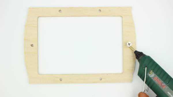
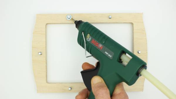
Step 7: Glue the screws in place
Once all the holes have been countersunk to the right depth, put a dab of glue to the side of each hole, and push a screw firmly in place.
The glue will stop the screw from rotating in the hole when the frame is in use. Any glue that gets into the thread can be picked out later, but firm seating is vital.
When all the screws have been glued in place, place the frame with threads up to attach the other half.
Step 8: Glue the washers in place
6mm washers need to be glued over each screw hole on one side of the other half of the frame. You could do this by placing the washers by eye, or you could fit the other half of the frame over the protruding screws first to ensure a good fit. If you do this, make sure that you do not let the glue stick both halves of the frame together by mistake!
Instructions For Full Version
