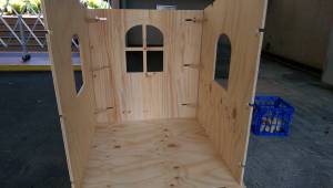
Cubby House Workshop
Cubbyhouse Project
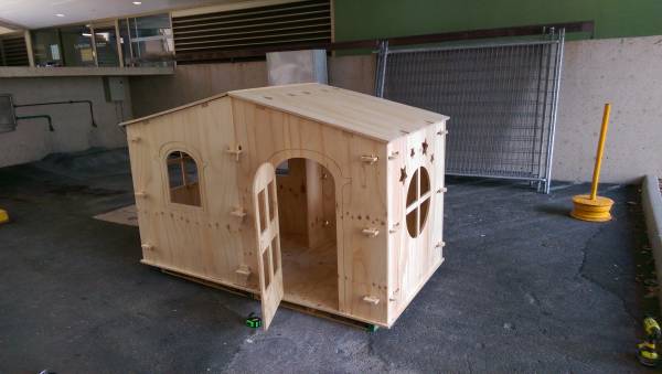
Build a Cubby house designed in Illustrator and cut using CNC over 5 weeks. This is an redevelopment of the Cubby House for Christmas project The Edge delivered in 2014-2015 with families that were clients/connected to The Smith Family.
Project Summary
Participants will - over five-to-six weeks - design and fabricate a custom cubby house out of plywood to take home. This will work from a base model that will be added to/subtracted from. Participants will work in small groups to achieve this. Current prototyping of the overall program will determine numbers that can be processed and final number of session required. It is intended that this project run continually throughout 2017, from March through December.
The new iteration of the project will seek to balance paying clients with clients from socio-economically marginalised communities. We are working with QLF to identify and approach companies that would be willing to donate materials. The aim is to make the program cost neutral, covering the costs of materials, equipment and facilitation in fees. Decorating of the final product will be the responsibility of the individual families.
Final designs will be showcased through The Edge's #madetoday stream and through the website. Participants will be provided with designs and the design files will be collected on The Edge website.
Activity Summary
Describe the activity being proposed and the engagement, skills and knowledge development value of this type of activity.
Materials
- 7x 2400x1200x15mm Plywood
- 1x 2400×1200 Aluminium Composite
- 6 meters 70x30mm Pine Stud
Tools
CNC Machine Cordless drill
Instructions
Step Zero:
Pre Process
I inherited the Illustrator files from the 1st round of cubby house project organised by Daniel Flood and Peter Musk. Some of problems that arose from the previous cubby houses, were the roof (Tarp and Rope) and building materials (painted MDF) and the large physical size.
So I decided to do 2 modular pieces roughly 1200×1200 and the participants can arrange them how they like. To try prevent weather damage we will be using sealed 16mm plywood which should be a bit more weather proof and aluminium composite for the roof. We also discussed the possibility of using Fusion 360 to create parametric design so the user could design there cubby house using set parameters but time constraint and having to learn new software within the time constraint was the issue but could be looked into for the 3rd version of the cubby house project.
Instead of starting from scratch with the design, I modified the existing illustrator files to a simple template with 2 moduler sections with a few options for window shapes and laser cut a 1/10 scale model from 3mm cardboard and assembled with hot glue . The obvious issues were the material thickness and joinery pieces being tiny, but the initial step gave me an idea of how much material was required, what parts went together and an idea of how it will look when its done.
I also made a 1/4 scale version to prototype on 3mm plywood as it would be close to scale material thickness and also the joinery mechanism could be tested out as well as gaining an understanding of efficient use of material. The next step is to build a full size prototype out of 16mm MDF to try iron out any unforeseen design issues such as make sure all sizes and tolerances and assembly were accounted for, clarifying what tooling is required and make necessary changes to the final template . Also a part of the pre planning for the the workshop, is to document the process for the setup of the CNC machine to use for induction purposes and to time how long the cutting process will take to estimate how to schedule the participants.
Moving the files to Enroute
After cutting the prototype I discovered a few errors with the design (mainly alignment issues overlooked in illustrator). Cutting time per sheet varied (simple cuts on full sheets no tool changes) aprox 15-20mins per sheet or panels with engraving took a little longer as I had to change tools from engraving to cutting on most panels as well as some technical issues with the tool bit becoming stuck in the spindle(see Troubleshooting).
Step One:
Each Participant will be given a template of the Cubby House and a selection of drag and drop shapes so they can sketch ideas they would like to try design in Adobe Illustrator. Once Participant is happy with the design sketch, they will start to add these shapes to the Adobe Illustrator template provided. The file is then opened in Enroute to create a tool path for internal and external routing and engraving. Lines that are pink are not completely joined. (Note-They can be fixed by shift+ click the shapes and right click→merge and raising the tolerance to a higher number until it turns blue)
Setting Toolpaths
To Set Tool Paths in Enroute including Internal routes(FEMALE), External routes (MALE) and engraving paths, the objects must show up BLUE. When a path is PINK, it means the objects path is not closed and needs to be fixed using the merge selection and raising the tolerances until the object turns BLUE.
Sending Files to CNC
After checking all the routing paths and you are ready to route, click on OUTPUT(G1) button. This is where you can set the Priority order in which the Router will cut ie. Engraving before routing or setting tooling orders.
Once you are done with setting the priorities, click on to file and save.
Open Multi Cam App Manager and open file manager
Click on Connect
Once connected find the file and send to machine.
Note:- the designer must also consider that the structural rigidity of the house could be compromised by cutting away too much material and highly detailed shapes will take more time to cut.
Step Two:
Turn on the CNC and it will run through the startup process(will take a few minutes). Then if the CNC machine has not been run on the day of use, run the spindle warm up (5 mins) Note-Make sure there is no tooling in the machine. When its finished warming up you can then insert the appropriate tooling and colette for the job. Go to the tool menu on the CNC controller and use upload tool tab. The Machine will then move to the tool installation area(keep clear from moving parts and potential pinch points). Select the routing bit you will be using from the menu Using the 2 spanners located with the CNC tooling. The machine will then run through a check by lowering the router bit to the sensor pad to determine the length of the router bit in relation to the bed. Note-Tool changes must be considered as you may need to change tooling eg engraving bit. Try to minimize tool changes by routing all the panels with no engraving first and change tooling when required.
Step Three:
Once all the parts are cut, apply a coat of clear urethane to seal the timber for added weather resistance and leave to dry.
Step Four:
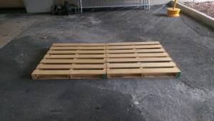
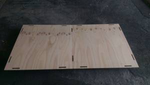
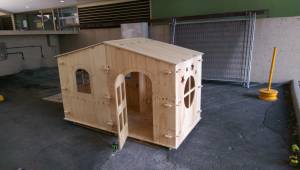
Place 2 pallets on the ground as a base and place the 2 floor pieces on top of the pallets.
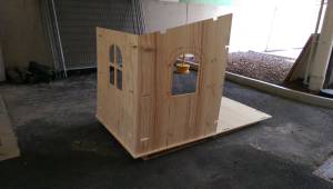
Starting in one of the corners, drop the 2 wall pieces into the slotted sections on the floor and assemble the 2 wall pieces using corner joinery.
Then place the 3rd wall on one of the bases and and assemble using the corner joinery install roof truss using 70×30 pine (4 required). Repeat for the other base.
Join the 2 bases together and its starting to take shape! Install central wall between the 2 bases.
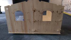
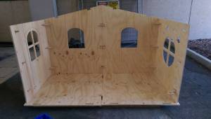 Add roof section
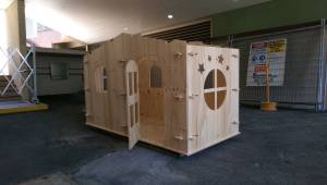
Step Five: Troubleshooting
Some problems encountered while designing the project
Material has not suctioned to bed-
Make sure bed is clean and relatively smooth. Try to use material that is not to bowed. If this is unavoidable, try place the material so its raised in the middle and push down the middle if this doesn't work, screw down into the waste board.
Cutting Small Pieces
When cutting smaller pieces you have to be very careful as small pieces can lift as the vacuum seal to the waste board reduces and they can be sucked up by the dust extractor or hit the router spinning at 16000rpm, throwing them from the machine.
Changing Tools
Remove the dust extractor that surrounds the spindle. The CNC tooling is very sharp and should be handled with care when especially when changing. Rusty tooling and dust can also seize in the tooling in the spindle so use the air compressor to blow dust from the collet. You can use a scour pad to remove some of the surface rust. Ensure you have selected the correct routing/engraving tool
Tooling Stuck in Spindle
If the tool does get get seized in the machine, try to remove the collet nut and use a piece of cloth wrapped around the shaft and try to loosen the collet by wiggling the router tool. If its still stuck, use a hard flat tipped object, ie screwdriver and hit downward with a bit of force, on the collet Tip:-Try have timber or a towel to soften the impact on the router bit.
You can add bridges to small pieces in Enroute which will leave a small tab to hold the object in place and break it out and clean it up with a file/linisher.
Right click on object and click edit this toolpath.
In Router Offset Parameters, Click on the “With Bridges” and set the parameters as needed.Tip:- set the height of the bridge to a minimum to avoid too much clean up of the dag afterwards.
Step Six: References
TryIt and Feedback
1. Feedback: Workshop plan needs some fleshing out and adaptation before we hand it over to someone else.
Solution: Depending on who we get for the AO5 gig (May 2017) this might be something we set them onto.
2. Feedback: Pairing users up and having them support one another cutting the cubby house out.
Solution: We control who they pair up with so that there is less like pairing with like. Each pair to assemble a Spotify (or similar) playlist of music to work by that will be shared through The Edge's social media networks. This will be a part of the workshops.
3. Feedback: Consider the community engagement aspect of the project and the community building; what part of this program delivers on that?
Solution: Step back and consider how this is building community; why will the come back? Why will they continue speaking to one another?
4. Other observations: I am not sure that this workshop couldn't stand to have two seperate people facilitating it; one on the design and community development aspect and one from the machining standpoint. I know we've taken the all in one approach and recall why we did that but wonder whether, on reflection now that we do not have the staff person imperative in place, this is the wrong way to go about it?
References
Critical Success Factors
Which of the critical success factors does this Prototype target? For more details see SLQ-Strategic-Plan-2016-20
Enable Access
- [✓ michael, 2016-11-22]Provide life skills and early childhood literacy programs
- Increase free access to digital content
- [✓ michael, 2016-11-22]Strengthen Queensland library infrastructure and discovery platforms
Engage Community
- Grow the State’s historical collection of Queensland culture and heritage
- Engage with communities of interest through dedicated centres of engagement
- [✓ michael, 2016-11-22]Facilitate the community’s use of and interaction with content
Build Capability
- [✓ michael, 2016-11-22] Build capacity within our communities of interest
- Generate new revenue sources
- [✓ michael, 2016-11-22]Position our workforce for the future
Delivering of The Edge Promises
Aside from the SLQ Strategic Plan, there is The Edge's commitments to the community and the lens we look at it through. Here are a few more check boxes for you to answer
This empowers creative experimentation across...
- Art?
- Science?
- [✓ mbyrne, 2018-11-01]Technology?
- [✓ mbyrne, 2018-11-01]Enterprise?
It will inspire...
- [✓ mbyrne, 2018-11-01]Whimsy?
- Nostalgia?
- Curiosity?
- Awe?
This were you put external links like LED generator
