Table of Contents
~~REVEAL~~
Soldering Induction
This induction has been separated hand tools induction to better cater for the needs of the public. The soldering induction is now focused on the different aspects of soldering and introduces users to a the different types of soldering as well as covering on what tools are recommended to use while working on a project requiring soldering.
The changes will take effect after July 2017 during the first half of the 2017-2018 Core Workshop program.
Summary
- Your Setup
- Soldering Irons; Cheap vs. Expensive
- Cleaning; Brass Wire pad vs. Slightly Damp Sponge
- Wire; Solid and stranded wire, 22AWG, Red, black + random color
- Solder; Thin vs. thick
- Desoldering braid
- Lighting
- Helping Hand
- Ventilation / Extraction
- The Basics
- Hold the iron Like a pencil but further up
- Never touch the metal part of the soldering iron
- Never leave or rest the soldering iron on a table, always use a soldering iron holder. Iron is very hot and things can easily catch on fire
- Don't eat while you're soldering, solder contain some nasty stuff which you don't want in your body
- Always use ventilation (Fan, draft, etc)
- Eye Protection is not required but highly recommended
- Always wash your hands after soldering
- While you're soldering
- Tinning
- Cleaning
- Types of soldering
- Wire soldering
- Through-hole soldering
- Surface mount soldering
Whats a good solder joint look like? here's Seed Studio's take on what you want and what you want to avoid
What do you do if it doesn't look right/
desolder using you desoldering braid“ or solder sucker but remember to not put too much heat in and fry your components (give the componets a rest tool cool off ) Notes**
- Visit the ESO’s in the Security office near the museum and pick up a hot work permit for the duration of the induction (plus half an hour)
- Ensure that the soldering kits contain the necessary tools and that the irons have usable tips before the start of the induction
- Ensure induction paperwork has been printed (Programming pod in staff area) and pens that can be found in the hurst behind the facilitators desk in the fab lab.
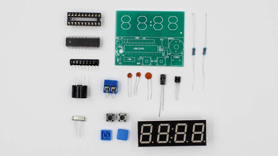
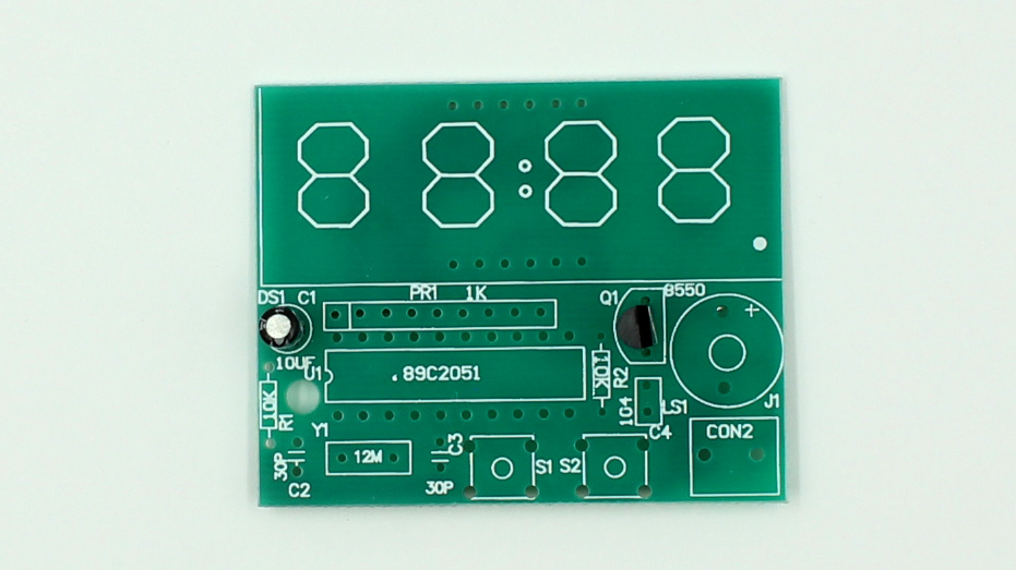
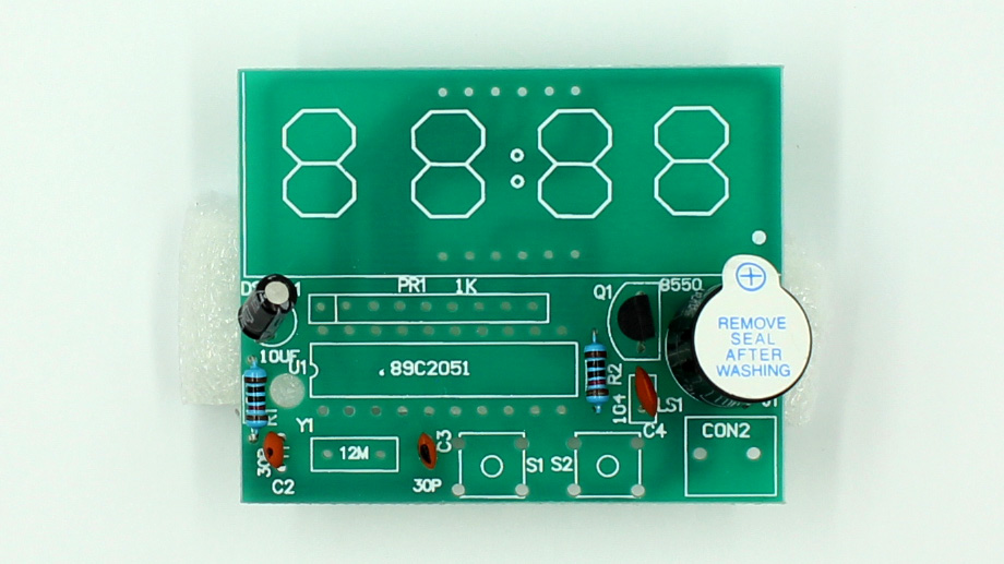
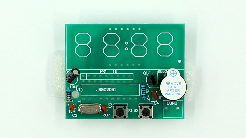
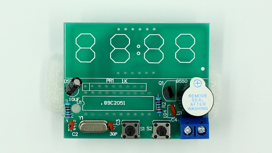
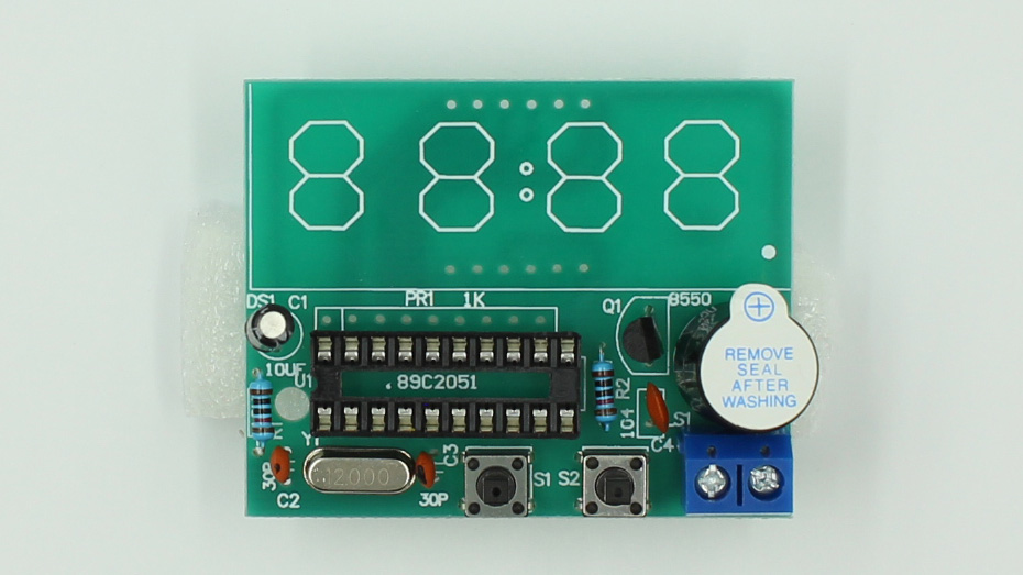
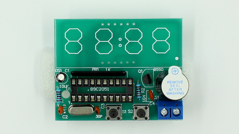
C51 Clock Kit Assembly
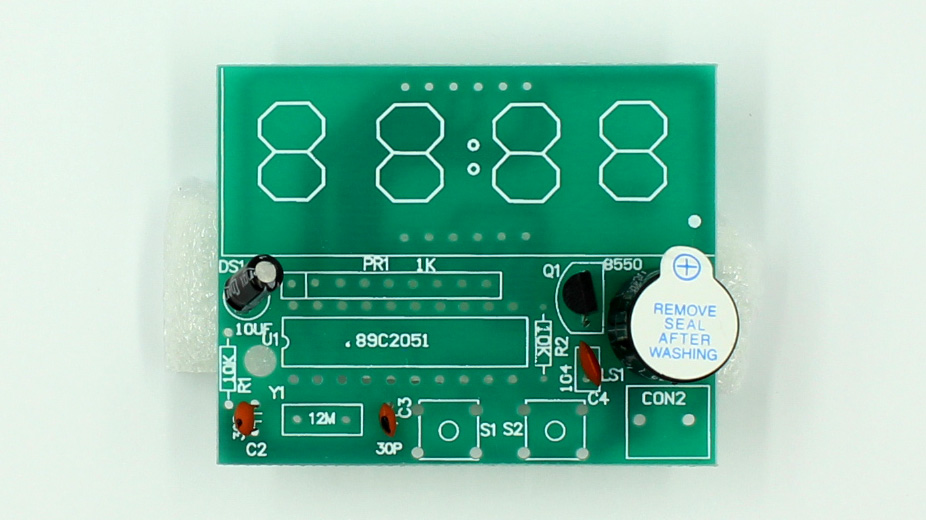
Capacitor (C1) and transistor (Q1). Make sure to put this in the correct direction.
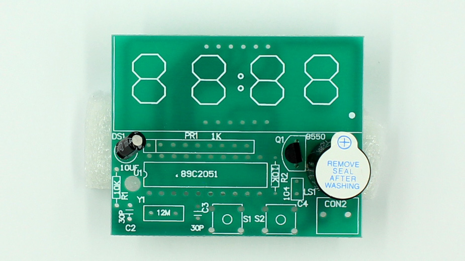
Piezo Buzzer (8550). Match up positive side with marks on board.
Capacitors, Large (C4), Small (C2,C3). Legs go in either way.
Resistors (R1, R2). Go in either way.
Momentary Buttons (S1,S2). Point legs out to the left and right. Quarts Oscillator (Y1).
Power Input Jack (J1). Make sure to face inputs outwards.
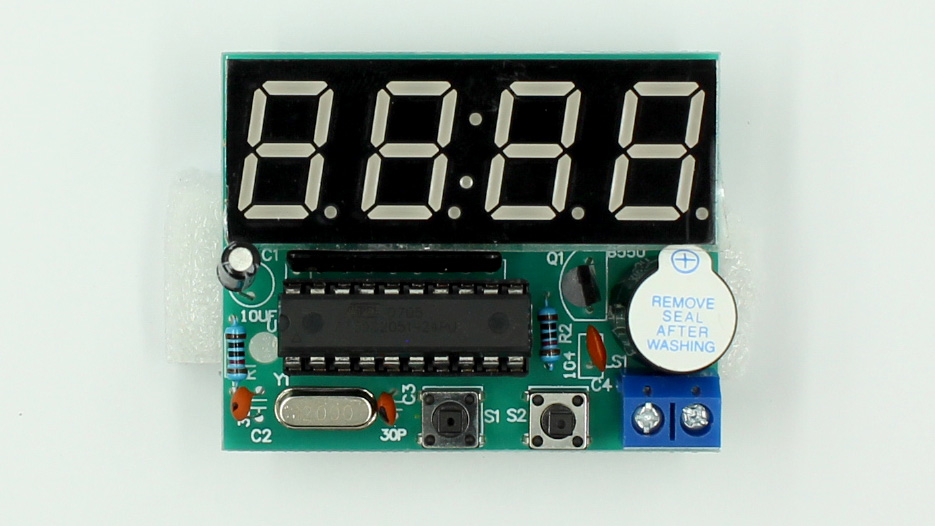
Integrated circuit (U1). Align notch with symbol on PCB.
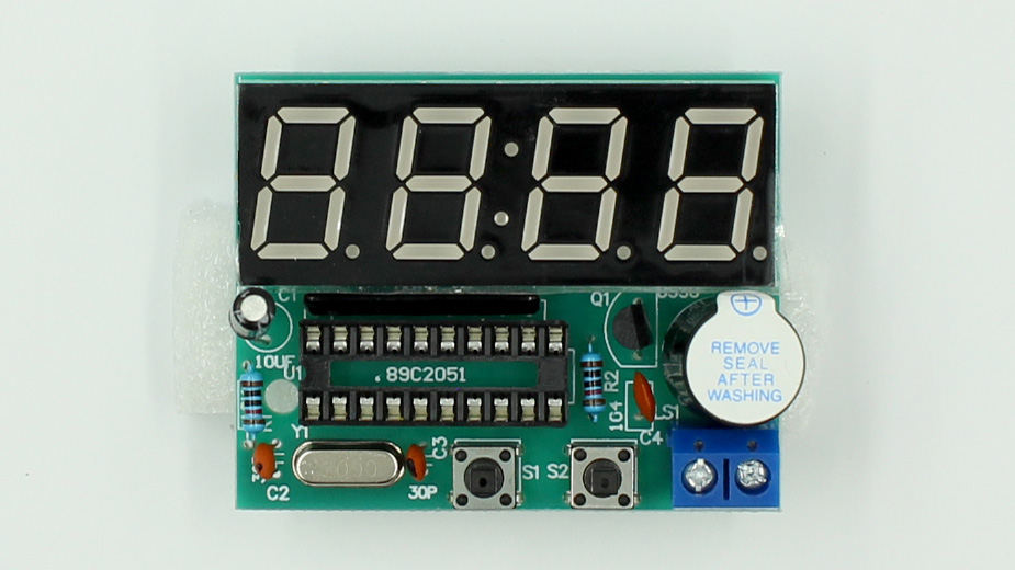
LED Display Controller (PR1)
LED Display (DS1)
Insert integrated chip, bend legs accordingly
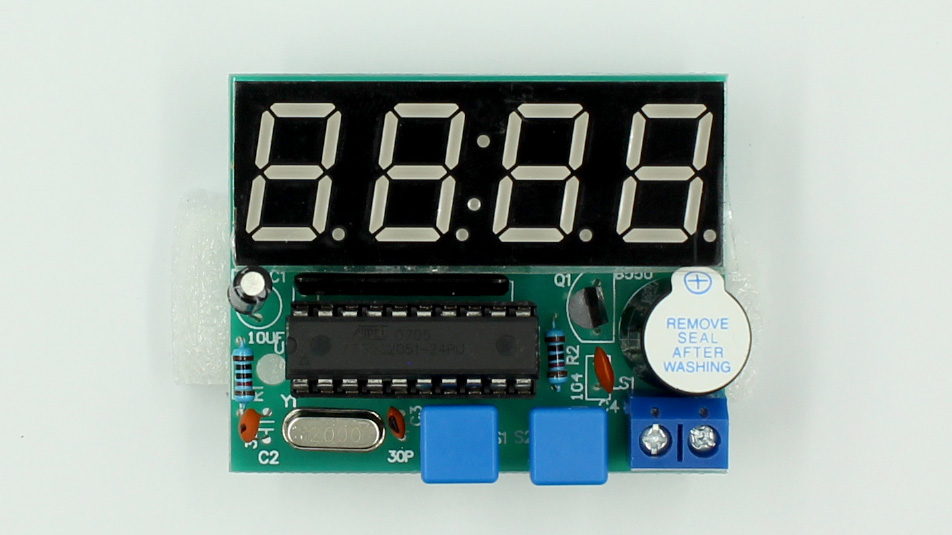
Attach blue button caps
Using the Clock
- Left Button changes mode
- Right button changes values
- Press and hold Left Button to edit mode
Modes:
- A - Set Hour
- B - Set Minute
- C - “Chime” / Alarm On/Off
- D - Alarm 1 On/Off
- E - Alarm 1 Set Hour
- F - Alarm 1 Set Minute
- G - Alarm 2 On/Off
- H - Alarm 2 Set Hour
- I- Alarm 2 Set Minute
