Table of Contents
Laser Cutter New Materials Testing Guide
Content
- Aim
- Method
- Approval to cut flow chart
- Notes on the flow chart
- Copper Wire Test Procedure
- Test Cut Procedure
- References
1: Aim
The aim of this document is to provide a guideline for the testing of the cutting and etching of new materials in the Edge’s Trotec 100w CO2 Laser Cutter.
Most of the tools in The Edge Fabrication Lab have been acquired with the intention of making these available to the public so members of our community can experiment with a range of fabrication technologies.
There is also an acknowledgement that members of the public and staff will want to experiment using different materials in equipment like The Edge’s Laser Cutter.
This section outlines a process to manage the risks of health hazards and damage to equipment that could occur from cutting/ etching different materials in the Laser cutter. These are guideline only and as such, do not cover all eventualities.
When testing new materials using the laser cutter extreme caution should be used.
Management of The Edge also reserves the right to the ban the cutting / etching of certain materials found to reduce the efficiency of the machine.
2. Method
The following Flowchart describes the process an authorized supervisor can undertake to assess a new material for approval to be cut/ etched on the Edge’s Laser cutter.
A: Approval to cut flow chart

B: Notes to the Flowchart
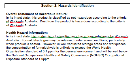
- Material Safety Data Sheet (MSDS/SDS) for the material. MSDS sheets can be obtained through Google searches or from http://www.msds.com. Examine the MSDS for ‘Hazards’ and ‘Hazard Identification’ sections, particularly hazards related to heating the material. For example from the Medium Density Fiberboard (MDF) MSDS:
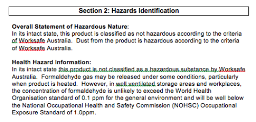
- While the laser cutter is equipped with a HEPA air filter, ALL gas release may be hazardous, so any unapproved materials releasing toxic fumes may not be used without express exception permission from senior management of The Edge
- If unsure of a material or the data contained within the MSDS, contact the manufacturer and enquire about laser cutting of the material
THE FOLLOWING MATERIALS ARE KNOWN TO BE HAZARDOUS AND CANNONT BE CUT
- Polyvinylchloride (PVC) based materials
- Materials containing melamine resins
- Plastics containing Nylon
- High Density Foam or other materials containing polyurethane
- MDF or Plywood or other materials containing either urea- or phenol-formaldehyde
- Foam-core board or other materials containing Polystyrene or Styrene
- If you are unsure of the type of plastic you are dealing with refer to http://www.chymist.com/polymers.html or to the charts below
- If the material is a reflective material such as a glass or mirror surface, it is recommended to cut from the non-reflective side if available
C: Copper Wire Test
- Use appropriate PPE (personal respirator, eye protection)
- If you haven’t performed this test before, use PVC sample in the kit to establish a positive result
- Obtain a piece of copper wire about 5 cm long. Push one end of the wire into a small cork. (The cork is used as a handle so you are not touching a hot wire)
- Place one plastic pellet or sample near your Bunsen burner. This is the sample you will be testing
- Hold the free end of the copper wire in the burner flame until it is red hot and the flame no longer has a green color
- Remove the wire from the flame and touch the hot wire to the plastic pellet or sample you will be testing. A small amount of the plastic should melt onto the wire. If the wire sticks to the plastic sample, use a pair of tongs to remove it. (You do not want to burn a large piece of plastic). Place the end of the wire, with the small amount of plastic on it, into the flame. You should see a slight flash of a luminous flame (a yellow-orange color). If the flame turns green in color, then the sample contains chlorine
- Needs sentence here about whether test is passed when chlorine is or is not present
D: Test Cut Procedure
- If the material is found to be suitable for cutting, set up the material and focus the laser as per standard Edge Laser Cutter Induction procedure
- In CorelDraw, create a small 20mm x 20mm square set to RED Hairline
- For low density materials or materials LESS than 2mm thick:
- In the Rayjet print preferences, set the RED CUTTING setting Power to 5% and Speed to 5% with a single pass
- Select skip in the BLACK ENGRAVING option
- Set ‘Move job to Laser’ in the laser print spooler
- Perform this cut
- Move laser to top left corner away from material
- Remove material and examine cut. Mark the Power and Speed settings in the format POWER/SPEED next to the cut. i.e. 5/5
- If the cut did not penetrate the material completely, perform the procedure again from Step 8 using an increment of 5% in Power
- It is important to make successive cuts next to each other in an ordered pattern and note the power/speed for each cut
- Repeat the procedure increasing the power until a complete cut is made. At this point, fine tune the settings using 1-2% increments or decrements, taking notes on the test material for each cut
- For high density materials or materials more than 2mm thick:
- In the Rayjet print preferences, set the RED CUTTING setting Power to 5% and Speed to 5% with TWO passes
- Select skip in the BLACK ENGRAVING option
- Set ‘Move job to Laser’ in the laser print spooler
- Perform this cut
- Remove material and examine cut. Mark the Power and Speed settings in the format POWER/SPEED next to the cut. i.e. 5/5
- If the cut did not penetrate the material completely, perform the procedure again from Step 8 using an increment of 5% in Power
- It is important to make successive cuts next to each other in an ordered pattern and note the power/speed for each cut
- Repeat the procedure increasing the power until a complete cut is made. At this point, fine-tune the settings using 1-2% increments or decrements, taking notes on the test material for each cut
- Once successful cuts have been made, examine the cut edges. If these are smooth and straight note down the cut settings for use. If the edges are melted or beveled / rounded, you may need to increase the passes, in which case, perform the procedure from the 5/5 % setting start again
- Once settings have been found for cutting, test for engraving as follows:
- In CorelDraw, create a small 20mm x 20mm square set to filled with BLACK
- In the Rayjet print preferences, set the BLACK ENGRAVING setting Power to 5% and Speed to 50%.
- Select skip in the RED CUTTING option
- Set ‘Move job to Laser’ in the laser print spooler
- Perform this engrave
- Move laser to top left corner away from material
- Remove material and examine engraving. Mark the Power and Speed settings in the format POWER/SPEED next to the engrave. i.e. 5/50
- If you are not happy with the engraving, perform the procedure again from Step 8 using an increment of 5% in Power
- It is important to make successive engraves next to each other in an ordered pattern and note the power/speed for each engrave
- Repeat the procedure increasing the power until a good deep engrave is performed. At this point, fine tune the settings using 1-2% increments or decrements, taking note on the test material for each engrave
- If 100% power is reached and with 50% speed and the engrave is not sufficient, set power to 90% and reduce the speed until desire engraving depth is reached
Sections 3, 4 and 5 above all say 'perform the test again from Step 8, but there is no Step 8 - re-write needed
As with normal operation, the laser cutter must always be monitored during operation in case of smoke, fire or flare up
3: References
Harvard Fab Lab, n.d. Laser Training Checklist, Retrieved 27 May 2015 from http://isites.harvard.edu/fs/docs/icb.topic1198394.files/training_checklist_LASER.pdf
David A. Katz, Identification of Polymers ©1998 Retrived 31 Aug 2015 http://www.chymist.com/polymers.html